Terminator3
Advanced Member level 3
Recently i found very interesting design. It was a super-cheap half-sized door opener sensor where only one patch antenna and one rat-race coupler is used. It is pretty confusing. Because there is usually also separate transmitting antenna.
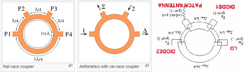
Assume rat-race have 4 ports ( https://www.microwaves101.com/encyclopedias/rat-race-couplers)
Port 1 is connected to LO oscillator
Port 2 and 4 connected to Schottky diodes
Port 3 is connected to patch antenna.

This is the most strange part to me. As we know, if signal is fed to Port 1, Port 3 will be isolated port. So how this single antenna is radiating?
LO signal at port 3 is cancelled.
My guesses:
1. maybe this rat-race coupler designed to work out-of band?
2. maybe some lengths are different from standard rat-race, so PORT 3 is actually in-phase?
3. https://www.qsl.net/yo4hfu/Files/TG/RAT RACE 1296 mixer.pdf
mayby it is not 3/4 lambda, but 5/4 lambda:

Assume rat-race have 4 ports ( https://www.microwaves101.com/encyclopedias/rat-race-couplers)
Port 1 is connected to LO oscillator
Port 2 and 4 connected to Schottky diodes
Port 3 is connected to patch antenna.
This is the most strange part to me. As we know, if signal is fed to Port 1, Port 3 will be isolated port. So how this single antenna is radiating?
LO signal at port 3 is cancelled.
My guesses:
1. maybe this rat-race coupler designed to work out-of band?
2. maybe some lengths are different from standard rat-race, so PORT 3 is actually in-phase?
3. https://www.qsl.net/yo4hfu/Files/TG/RAT RACE 1296 mixer.pdf
mayby it is not 3/4 lambda, but 5/4 lambda:
Last edited: