Continue to Site

Welcome to EDAboard.com

Welcome to our site! EDAboard.com is an international Electronics Discussion Forum focused on EDA software, circuits, schematics, books, theory, papers, asic, pld, 8051, DSP, Network, RF, Analog Design, PCB, Service Manuals... and a whole lot more! To participate you need to register. Registration is free. Click here to register now.

Offline power supply design

Status
Not open for further replies.

mmuj

Junior Member level 3
Joined
Jul 11, 2006
Messages
26
Helped
0
Reputation
0
Reaction score
0
Trophy points
1,281
Activity points
1,538
Hi

I have to design a power supply as a part of a bigger system but I have no experience of high voltage power supply design.

I am looking for a reference design for high voltage low/medium power, isolated power supply.

Requirement specs are

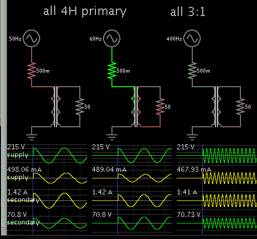
VIN Range = 150V to 650V, 50/60Hz, 400Hz is an optional

VOUT = any thing between 24V and 48V

Output Power = 50W

Thanks and Regards,

M Mujahid
 

What do you mean by reference design?

I ask only because this subject is more lethal than most other subjects seen on this site, you really should not attempt to implement a reference circuit without proper research and the first thing to research may be safety.

I don't know you might already be knowledgeable about that but you wrote "but I have no experience of high voltage power supply design.", now I am not the best person to advice you about this(I shouldn't advice you about any circuit related stuff in this case), and this isn't any advice regarding the circuit but I just want to advice you to be careful, very careful because it's dangerous.

What experience do you have besides not having any experience of high voltage power supply design?

- - - Updated - - -

What do you know about DC-DC converters/SMPS?
 

Thanks David for reply

I have a reasonable experience of product designing, especially products for high temperature, intrinsic safety, high speed etc but no high voltage design. high voltage switching power supply is just a small part of my current project.

I have used quite a few DC-DC switching regulators in my designs, buck, boost, sepic etc but all below 60V.

Reference design provided by chip manufacturer are usually a good staring point although they need to be tweaked and tested for required results.

I just need a good starting point so that i can do some search, calculation, simulation and then have design reviewed by someone before any attempt to build and try on mains.

I have tried to find offline switch controller but they are usually for up to 450V. I was wondering if I have to do something to drop voltage or float the controller to keep it below below maximum rating.


Regards,

MM


Then a transformer is the usual answer. It can be the first component, stepping down the AC supply, or else it can be part of a flyback.

This is just a first outlook on how to design your project. The job is complicated by your wide choice of input and output voltages. You'll probably want to consider a few topologies, see how each one gels, then choose the topology which is most suitable.
 

A Step down transformer is my last option, as operating frequency could be 400Hz.
I probably stick with flyback topology, output power requirement is well under 100W.
any suggestion on controller and MOSFET?
 

A Step down transformer is my last option, as operating frequency could be 400Hz.

According to this theoretical simulation, you can design a transformer to operate safely at a slower AC frequency, then you can speed up the frequency without losing much performance.


An alternative is to make a full diode bridge as your first stage. Then send (rectified) DC to a flyback operating at various duty cycles. You'll have components carrying 650V (or else 919V peak based on 650 x 1.414?). High voltage spikes are liable to rise more than 1000V. Arcing between windings is likely. Once there is a single incident of arcing, it becomes more persistent.
 

This on-semi ap note covers most of your requirements.

As others have said, very dangerous.
 

Attachments

  • flyback complete design wide voltage input on semi AN1327-D.PDF
    323.1 KB · Views: 64

I wrote: Arcing between windings is likely. Once there is a single incident of arcing, it becomes more persistent.

Would you mind expanding that statement?

My old tube oscilloscope developed arcing in a transformer after it was stored in a humid basement for a while. There was a 6.3VAC winding in contact with 1000V (from the high-voltage section). It started as a few clicks per second, but once the 'singing' started, it would not go away. I might get a minute's use after powerup, and then the singing rendered the scope useless. Furthermore the arcing rose in pitch. This implied the path was getting easier for sparks to jump (despite the fact the scope was in dry air).

I cured it by installing a separate 6.3V transformer and supplying the high-voltage section. It worked fine until I again stored the scope in the humid basement. Since I saw it happen to two transformers, it tells me that 1kV is just about at the threshold voltage for this phenomenon. I had to replace it with another 6.3V transformer to cure it.
 

As its part of a bigger system, it sounds like size and weight is not a major consideration.

All things considered, I would be thinking about a toroidal mains transformer with several primary tappings, like 150v, 300v, 650v as a first step.
Grain oriented silicon steel wound toroids work fine at 400 Hz, in fact they will be more efficient than at 50/60 Hz.

That will also be a big plus for mains isolation and safety. And it takes care of the rather wide input requirements pretty simply.

A fairly conventional buck regulator on the output should easily cover the
24v to 48v output requirement.

It should be pretty easy to design something that is robust, reliable, and simple.
 

My old tube oscilloscope developed arcing in a transformer after it was stored in a humid basement for a while. There was a 6.3VAC winding in contact with 1000V (from the high-voltage section). It started as a few clicks per second, but once the 'singing' started, it would not go away. I might get a minute's use after powerup, and then the singing rendered the scope useless. Furthermore the arcing rose in pitch. This implied the path was getting easier for sparks to jump (despite the fact the scope was in dry air).

I cured it by installing a separate 6.3V transformer and supplying the high-voltage section.

Same thing happened to me and i used the same fix.
 
Thanks for comments,

Either I will go to ONSemiconductor route or use toroidal transformer after looking in it other implication, i.e. size, time, risk etc.


Will update late


Regards,

M Mujahid
 

Input 150V to 650V (lowest to highest)

Output 24V to 48V (lowest to highest)

Worst case: input 150V, output 48V, power 50W (ratio: 3 to 1)
Other extreme: input 650V, output 24V, power 50W (ratio: 30 to 1; approx)

Max current (output): 2A
Max current (input): 0.3A

It is possible but messy. You will not have much margin on either side.
 

Status
Not open for further replies.

Part and Inventory Search

Welcome to EDABoard.com

Sponsor

Back
Top