Continue to Site

Welcome to EDAboard.com

Welcome to our site! EDAboard.com is an international Electronics Discussion Forum focused on EDA software, circuits, schematics, books, theory, papers, asic, pld, 8051, DSP, Network, RF, Analog Design, PCB, Service Manuals... and a whole lot more! To participate you need to register. Registration is free. Click here to register now.

feedback control for SMPS using ICE2QR2280G

Status
Not open for further replies.

dann11

Full Member level 3
Joined
Oct 22, 2015
Messages
166
Helped
0
Reputation
0
Reaction score
0
Trophy points
1,296
Activity points
2,742
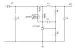
Hi! just noticed that in this SMPS design(using ICE2QR2280G as PWM controller) the feedback controller which is the optocoupler is connected in between the diode rectifier and the inductor filter, why it connected in there? is this common to all SMPS circuit? Can it be connected across that output since it is monitoring the load power for regulation and overvoltage sensing.. thanks..View attachment Infineon-ICE2QR2280G-1-Demoboard-AN-v01_01-EN.pdfView attachment Infineon-ICE2QR2280G-1-Demoboard-AN-v01_01-EN.pdf
 

I wonder if there is drawing mistake on the schematic. Something around the opto's cathode return seems strange. I tried to verify with the actual PCB layout, but it is not that easy to follow. Normally, pin 2 will be connected to the cathode of the TL431 as shown below.
 

Attachments

  • TL431.png
    TL431.png
    7.7 KB · Views: 103

I wonder if there is drawing mistake on the schematic. Something around the opto's cathode return seems strange. I tried to verify with the actual PCB layout, but it is not that easy to follow. Normally, pin 2 will be connected to the cathode of the TL431 as shown below.

yes, the TL431 is connected with the pin2 of the optocoupler..
 

The drawing is ok, its just that their connection of rbias is doubtful, you really need to have a resistor across the opto diode, because like its connected there in post#2, the rbias will likely not get sufficient current through it when the smps is on full power.

Anyway, the connection configuration OP speaks of is called the “fast lane, slow lane” connection, and yes, the opto diode does need to be the upstream side of the output filter inductor

Ill post you some refs on this soon

- - - Updated - - -

here is a post on it, with the docs linked
https://www.edaboard.com/threads/353203/
 
  • Like
Reactions: dann11

    dann11

    Points: 2
    Helpful Answer Positive Rating
The L21 & C23 forms a post filter to reduce ripple / noise on the output this is typical in flyback designs & very difficult to compensate most of the times, refer attached PDF for detailed analysis
 

Attachments

  • AND8327-D.pdf
    202 KB · Views: 94

As you know, the output LC filter isnt difficult to handle as long as its corner frequency is well above the crossover frequency of the smps..Preferably three times higher at least.
 

Yes you are correct treez but getting sufficient ripple attenuation & maintaining filters corner frequency 3 times higher is the tricky part / difficult part of the design particularly if your loop crossover
requirement is higher for fast dynamic response.
 

Status
Not open for further replies.

Similar threads

Part and Inventory Search

Welcome to EDABoard.com

Sponsor

Back
Top