Continue to Site

Welcome to EDAboard.com

Welcome to our site! EDAboard.com is an international Electronics Discussion Forum focused on EDA software, circuits, schematics, books, theory, papers, asic, pld, 8051, DSP, Network, RF, Analog Design, PCB, Service Manuals... and a whole lot more! To participate you need to register. Registration is free. Click here to register now.

difference between rising time and falling time in pulse response of transmission line

Status
Not open for further replies.

lawfulgm

Junior Member level 1
Joined
Jun 9, 2009
Messages
16
Helped
0
Reputation
0
Reaction score
0
Trophy points
1,281
Activity points
1,426
Hi all,

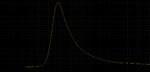
in high-speed serial link design, we usually see more # of post-cursor ISI than pre-cursor ISI.

The attachment is output pulse response of s-parameter channel I have. input is an ideal pulse with bit rate of 25 Gbps.
As shown in the attachment, we see that slope of rising edge is clearly faster than the slope of falling edge.

Does anyone know why this happens from physics perspective?

Thanks,
 

Attachments

  • channel_response.png
    channel_response.png
    15.4 KB · Views: 103

When I see behavior like this on occasion, and I can't figure out the reason, I tell myself that 0V is a neutral, 'less active' force pulling downward, in contrast to the 'active' force which pulls upward. Therefore the downward slope is slower than the upward slope. It's just a naive hypothesis, not a satisfactory explanation. It's a first effort toward a sensible explanation.
 

You would use symmetrical pulses or edges with sufficient period if you want to see symmetrical (equal) rise and fall times.

S-parameter channel description are presuming a linear model and don't involve non-linear signal distortion. What you see is dispersion transformed to time domain.

- - - Updated - - -

To see real rise and fall times, you'll convolve the pulse response with a square wave (or may be a bit pattern) of reasonable signal rate. You'll see that the width of the pulse response represents the rise and fall time of the real signal. The non mirror-symmetrical pulse response appears as a long tail in the edge shape.

As a simple example, look at the pulse response and step response of a first order low pass and compare it to a filter with almost gaussian pulse response (like a higher order Bessel LP).
 

Thanks a lot for your inputs.

To FvM:
This output pulse, however, is result from symmetrical ideal pulse with rising and falling time of 5 ps.
Then the question is, if it is happened due to the dispersion, why do we have asymmetrical behavior between rising and falling edge? rising edge should also experience this dispersion behavior.
In addition, in my opinion, even if dispersion distorts the signal, non-linearity should partially cancel the distortion effect (soliton)

Gaussian pulse response would not experience this asymettrical behavior by its definition and its mathematical model. FFT of gaussian shape in time domain would result in gaussian shape frequency response. This is already implying that both of rising and falling edge of gaussian behavior are symmetric.

1st order Low-pass filter behavior would not mimic this effect as well because both of rising and falling time is exponentially increasing & decreasing (we can prove this mathematically using differential equation).

My question is to answer the reason why the non mirror-symmetrical pulse response appears as a long tail in the edge shape... not to see the rising and falling time.
But you've got the good point: S-parameter channel description are presuming a linear model and don't involve non-linear signal distortion.
What if the s-parameter file I am using is generated based on somewhat non-linear channel characteristics? would it be the cause of this problem?
 

I don't see why nonlinearity is needed to explain this. If your pulse is so short that the system doesn't approach a steady state, then a simple lowpass filter will show results like that. In fact, a perfectly symmetric response could only result from an anticausal system, so there's no reason to expect such a thing.

- - - Updated - - -

1st order Low-pass filter behavior would not mimic this effect as well because both of rising and falling time is exponentially increasing & decreasing (we can prove this mathematically using differential equation).
The waveform you show can be approximated by exponential functions. On timescales much less than the time constant, the response will look like a linear ramp, like with your very short pulse.
 

This characteristic is coming from a series resistor (ohmic resistance of the line) and a shunt capacitor (stray capacitance of the line). The only way to improve the pulse response is to minimize this stray capacitance.
Stray capacitance is necessary in transmission lines to form (and to keep) a specific line impedance.
But specific impedance transmission line is not always mandatory, and the stray capacitance can be minimized by removing nearby (and under) grounds, and as well the trace width (not too much because the else inductance will increase).
Regarding your last question, is hard to believe that here is about a non-linear signal distortion.
 

great replies. Thanks a lot guys!

After several simulations with all your feedback I think I finally found out the answer:
like some of you mentioned, rising edge was not hitting to its final value. output pulse started getting collapsed before it hits its steady-state, hence the output pulse was distorted.

Thanks a lot !
 

Status
Not open for further replies.

Part and Inventory Search

Welcome to EDABoard.com

Sponsor

Back
Top