Continue to Site

Welcome to EDAboard.com

Welcome to our site! EDAboard.com is an international Electronics Discussion Forum focused on EDA software, circuits, schematics, books, theory, papers, asic, pld, 8051, DSP, Network, RF, Analog Design, PCB, Service Manuals... and a whole lot more! To participate you need to register. Registration is free. Click here to register now.

[SOLVED] 1-Wire thermometer not working in parasitic mode (DS9490R and DS18B20)

Status
Not open for further replies.

harvie

Full Member level 1
Joined
Sep 10, 2014
Messages
98
Helped
2
Reputation
4
Reaction score
2
Trophy points
1,288
Location
Prague
Activity points
2,485
Hello,
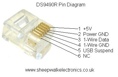
i have DS9490R USB dongle. It's USB to 1-Wire interface. I use it to run powered network of DS18B20 thermometers and it works as expected. However it does not work in parasitic power mode. (2 wires instead of 3).

Datasheet of DS18B20 tells me to connect both VCC and GND pins to ground wire of bus and DQ pin to data wire of bus. It should then get some power from the data pin instead of external power supply pin. You can find people on internet that succesfully use this setup. For me it's not working.

When i wire the probe in parasitic manner it just shorts whole bus and other chips disappear from it. I tried this with different thermometers from different vendors. I am also sure that i have wired it as is supposed. It does the same no matter if i connect the sensor directly into dongle or using my 1-Wire network (cca 15m of cables and splitters).

Do you have any idea why this should not work? Should i RMA the dongle?
 

It is not correct to connect BOTH VCC and GND together. It is possible to get some power from the data pins.
 

It is not correct to connect BOTH VCC and GND together.

It's in datasheet like that. It says: "VDD must be grounded for operation in parasite power mode."
Of course i didn't shorted VCC and GND of bus. I've shorted VCC and GND of sensor.

parasite%20power%20conection%20diagram.png


They even sell version called DS18B20-PAR that has VCC and GND connected internally for convenience:

203Fig03.gif
 

In parasite mode VDD (at the device pin only) and GND should be joined but there is another consideration, quoting the data sheet:
In some situations the bus master may not know whether the DS18B20s on the bus are parasite powered
or powered by external supplies. The master needs this information to determine if the strong bus pullup
should be used during temperature conversions. To get this information, the master can issue a Skip ROM
[CCh] command followed by a Read Power Supply [B4h] command followed by a “read time slot”.
During the read time slot, parasite powered DS18B20s will pull the bus low, and externally powered
DS18B20s will let the bus remain high. If the bus is pulled low, the master knows that it must supply the
strong pullup on the 1-Wire bus during temperature conversions
Your problem is almost certainly insufficient current available on the data line, especially when more than one device is connected to it. The data sheet explains how to boost the available current using a MOSFET to 'pre-charge' the internal supply storage capacitor but it may not be practical to implement it using your USB interface.

Brian.
 

I've tried to pull up the data wire using 3k3 resistor without getting any better. The MOSFET idea of strong pullup is interesting. I don't know if DS9490R does not have such MOSFET by itself and i don't know how to trigger it by the dongle. I could do some intermediate box with mosfet pullup and possibly esd protection and other fancy stuff i'd like to put between dongle and network. However i am not sure if some of these pins can be used for controlling mosfet:

fetch.php


It's probably meant for microcontrollers or devices with GPIO pins that can control MOSFET to pull bus up before each readout. Not sure how can i implement this on dongle.
 

I do not think it is possible because you need an additional logic output and also some way to control it but you could use the +5V from the USB plug (pin 1) to power the DS18B20 in NON parasitic mode.

Brian.
 

you could use the +5V from the USB plug (pin 1) to power the DS18B20 in NON parasitic mode.

Yeah, that's exactly how am i doing it right now.

However i am not sure if problem does not lay in cheap DS18B20 sourced from aliexpress for $0.7 piece. I'll try to source DS18B20 from local electronics store to compare it. But i've googled and didn't find any explicit statement that there are fake chinese DS18B20s that have problem with parasitic power. But maybe most people are using separate power, so they didn't noticed.
 

VCC and VDD are not necessarily identical. Connecting Vdd to ground at the device end is fine. Then you need to connect only the ground and data pin- leave the third pin hanging (not connected to the USB pins.
 

c_mitra, in "parasite power" mode the VDD at the device has to be connected to ground but obviously isolated from the incoming +5V so it doesn't short it out.

The internal power supply for the DS18B20 draws from both VDD and the DQ pin so it will power itself from either pin but the VDD pin has a voltage sensor on it that detects whether an external VDD is connected. Parasite mode is detected when the VDD pin does not have voltage on it and the manufacturer recommends it is grounded to ensure that.

The data sheet for the DS9490R suggests it can provide enough current to power devices in parasite mode but there is a real risk that it or the sensors are fakes.

When I use several DS18B20 in parallel I use 5V VDD and add a 100nF capacitor across each device. When I have to use long cable runs I use a small 1-wire to serial converter (a PIC10F202 and one capacitor!) and I've had it working over several hundred metres but only one device per serial link can be used.

Brian.
 

I've just checked and the problem was really caused by fake chinese DS18B20 chips. I've also created simple test to tell if your device is fake.

1.) Connect to your bus master
Fake does not work in parasitic mode while original does :) In fact fake will put down whole bus.

2.) Test using multimeter (i guess most reliable)
Diode test: + lead on DQ, - lead on DCC. Original DS18B20 will show nothing, fake will show approx 1.4V drop.

3.) Test powered devices using computer to find them in your network
default errata/trim value of fake devices is always 65535 while on real thing it can vary
default templow/temphigh values of fake device is -1/-1, while 70/75 on original?

I've written more info here:
**broken link removed**
 

Status
Not open for further replies.

Similar threads

Part and Inventory Search

Welcome to EDABoard.com

Sponsor

Back
Top