Continue to Site

Welcome to EDAboard.com

Welcome to our site! EDAboard.com is an international Electronics Discussion Forum focused on EDA software, circuits, schematics, books, theory, papers, asic, pld, 8051, DSP, Network, RF, Analog Design, PCB, Service Manuals... and a whole lot more! To participate you need to register. Registration is free. Click here to register now.

AC current measurement using ACS712 current module and PIC16F877A

Status
Not open for further replies.
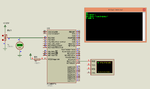
@pic.programmer..my hardware is simple as I showed in first post where I asked question about it.

I think there is no problem in your coding and my coding everything is ok.....problem is in Hardware/circuit designing....you must see this.

View attachment AC curent mesurement.rar

this is arduino based project take look on ACS712 module and ADC interfacing ..they used opamp for it!
 
Last edited:

Maybe your sensor is damaged. See the attached image. It clearly shows that for adc input 925 mV it shows 5.0A.

It is the result of Rev1 file that I posted in my previous post.

No need for an OpAmp. The sensor gives 185 mV / A AC / DC. Measure the voltage at the input of ADC for say 1 or 2 A current through the sensor and post the readings. You have to measure in mV range.
 

Attachments

  • ACS712 AC Current Measurement 2.png
    ACS712 AC Current Measurement 2.png
    35.3 KB · Views: 142
Last edited:

I will try to implement this code for you.

http://www.puntoflotante.net/ACS712-CURRENT-SENSOR-FOR-18F2550.htm

http://www.sunrom.com/p/current-sensor-20a-acs712

- - - Updated - - -

Edit:

I have implemented this code

http://henrysbench.capnfatz.com/hen...surements/acs712-arduino-ac-current-tutorial/

for PIC. I know you are using Hi-Tech PICC. I have written code using mikroC PRO PIC Compiler. If the .hex file works fine for you then I will port the mikroC PRO PIC Code to Hi-Tech PICC code and post it here.

The attachment also includes Proteus Simulation file.

The method mentioned in the above link uses Sensor connected directly to PIC (or Arduino). No OpAmp Circuit is used. Calculations are done in the code.
 

Attachments

  • ACS712 AC Current Measurement Timer Method Rev1.rar
    41.8 KB · Views: 133
Last edited:

I will try to implement this code for you.

http://www.puntoflotante.net/ACS712-CURRENT-SENSOR-FOR-18F2550.htm

http://www.sunrom.com/p/current-sensor-20a-acs712

- - - Updated - - -

Edit:

I have implemented this code

http://henrysbench.capnfatz.com/hen...surements/acs712-arduino-ac-current-tutorial/

for PIC. I know you are using Hi-Tech PICC. I have written code using mikroC PRO PIC Compiler. If the .hex file works fine for you then I will port the mikroC PRO PIC Code to Hi-Tech PICC code and post it here.

The attachment also includes Proteus Simulation file.

The method mentioned in the above link uses Sensor connected directly to PIC (or Arduino). No OpAmp Circuit is used. Calculations are done in the code.
The problem is same as previous.again different values coming!!!
This is what I got from your code ACS712 AC Current Measurement Timer Method Rev1.rar.
12921107_10209300416291191_2023774049_n.jpg
I told you before that problem is not in coding whatever you programmed...Its in Circuit designing....I need To implement Opamp Circuit for that I will let you know after researching on it (and let me know too if you got anything) we will continue this unsolved thread!! The problem I have getting is same problem occurred to many others I have seen too many threads on this topic.....Thanks for your valuable time..Much appreciated.
 

Ok. You provide the OpAmp Circuit and I will write the C Code. The OpAmp Circuit you mentioned is from the ACS712 datasheet that is what sunrom.com mentioned when I contacted them.

They said they have not tested that circuit. The same circuit was mentioned in your instructables page but they don't provide circuit and I have no time to calculate the output voltage of the OpAmp theorotically. You please buile the circuit and tell the output voltage of OpAmp for any known current through the sensor. i will then write code for you.

Okay.Got it!
 

I will implement this method in code. You send me the three voltages you get for three different wattage bulbs and also the voltage for 0 current.
 

Status
Not open for further replies.

Similar threads

Part and Inventory Search

Welcome to EDABoard.com

Sponsor

Back
Top