Continue to Site

Welcome to EDAboard.com

Welcome to our site! EDAboard.com is an international Electronics Discussion Forum focused on EDA software, circuits, schematics, books, theory, papers, asic, pld, 8051, DSP, Network, RF, Analog Design, PCB, Service Manuals... and a whole lot more! To participate you need to register. Registration is free. Click here to register now.

Simple questions on RS232 interfacing

Status
Not open for further replies.

smartsarath2003

Member level 4
Joined
Feb 12, 2004
Messages
77
Helped
2
Reputation
4
Reaction score
0
Trophy points
1,286
Activity points
1,061
rs232io.exe

Hai,

I am a new guy to serial port protocols. I want to connect an LED to a serial port and want to switch it ON when a specific/any key press occurs on key board.

If I start hyper terminal and start new connection with my serial com port, Can i observe any data on Transmitt (pin-3) of RS232 when any key is pressed :?: .

I actually tried to send a txt file with a single char. But after a long time, hyper terminal comes up with message remote device not found message. As I actually don't want to communicate with any device and i don't mind sending some rubbish.
But my idea is to send oxff to switch on led and 0x00 to switch off.

can anyone please explain me the above points... :roll:

Thanks
 

serial port relay

Try to use "no flow control" and check your connection to the serial output and input are pull up.
 

using rs232 dtr to drive a relay

Hai,
Iam not sure how to enable "no flow control" from Hyperterminal. Also I didn't have anything/any pull ups conncted to serial port.
Iam just trying to send some char out through rs232 and want to check the data pin with scope. I just want to know weather it is possible to use serial port like that.

The application I am trying to use was some thing like the attached ckt. In that parallel port was used to drive the relay and I want to replace that with a serial port. With parallel port , i just need to make the corresponding data pin high. But looks lil confusing with serial port.
Any help?

Thanks
 

Attachments

  • lpt_ssr_114.gif
    lpt_ssr_114.gif
    6.3 KB · Views: 657

smartsarath2003 said:
Hai,
Iam not sure how to enable "no flow control" from Hyperterminal. Also I didn't have anything/any pull ups conncted to serial port.
Iam just trying to send some char out through rs232 and want to check the data pin with scope. I just want to know weather it is possible to use serial port like that.

The application I am trying to use was some thing like the attached ckt. In that parallel port was used to drive the relay and I want to replace that with a serial port. With parallel port , i just need to make the corresponding data pin high. But looks lil confusing with serial port.
Any help?

Thanks

You need to do low level serial port IO. You cannot just send data as after the data is sent the led will turn off. Instead use the DTR or RTS pin and set it high or low using the EscapeCommFunction call in windows api.

See https://www.connecttech.com/KnowledgeDatabase/kdb229.htm for function details.
 

yes, you should connect that signal (input to your relay) to the DTR or RTS (which are also outputs). Serial transmit may not be good since there will be some ON/OFF state in the sending of a byte.

Another point to note is the voltage level of the serial output may 9V. Check out beyond logic for more information.

**broken link removed**
 

the serial port is actually controlled by a USART chip or equivalent SuperIO chipset in the motherboard. the chip needs to be programmed first like the data byte to send, the baud rate, etc. truth is, you cannot program the TX pin to stay in single state. what happens is that you first load the data into one of the USART's registers and then trigger the USART to send the data at the specified baud rate. for more info, read the link given by kasd to learn more about the serial port. just hit me for any questions and i'll try to answer them. enjoy with your experiments!
 

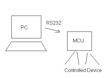
To control devices thru rs232 I suggest you use a microcontroller to interpret the data that you are sending specially if you intend to control more that one device.

84_1178254981.jpg
 

you can use as already sayd DTR or RTS ( outputs), at ouput pin you can use a low current led with a series resistor 3k3ohm because current must be lower 2milliamperes/pin to be able with desktop and notebook.
 

what hardware (circuit) would you recomend to test the port software
 

what do you mean by " only jumpers between inputs and outputs " ? can you be a bit more specific.
 

all TXD-DTR and RTS are 3 outputs and can be connected with 4 inputs DCD CTS DSR and RI .
you can with a program rs232io.exe set every output and if itis connected with a input(jumper) you can test that output and that input the red point become green.
 

Hi turbina,

let me see a sketch(circuit) to implement the TXD-DTR and RTS as outputs , and DCD CTS DSR and RI as inputs

thanks
 

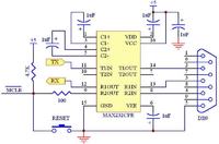
you can see a interface with max232 that convert ieee rs232 signal level to ttl level (0-5volts) after tou can drive a led, a pin port of microprocessor o logic, the current sink of max232 is 5milliamperes , you can take the 5volts for max232 from pin 1 and 4 of a free usb-port.
 

Hi,
I am a newbie ..i am interfacing MCU atmega8l to PC through RS232 ,here i did the loop back test via hyperterminal i didn't get the response from the MCU.
And before communicating to mcu i did the loop back test to the following for these i got the response

Start from the cable and work you way over to the PIC. Use hypertem to do a loopback in each of the following steps. I understand that step 1 will pass and step 4 will fail in your case.

1. Remove the RS232 cable from the Inchworm and short pins 2 and 3 on the cable.

2. If step 1 passed: Remove the MAX232. Look at the schematic and determine which pins on the MAX232 socket connect to 2 and 3 on the DB9. Short these pins at the MAX232 socket. If this works you know the RS232 signal is getting to the MAX232. If not you have bad solder joints between the DB9 and the MAX232 socket.

3. If step 2 passed: Replace the MAX232 and remove the PIC. Short the MAX232 pins that go to TX and RX on the PIC at the MAX232 chip. If this works your MAX232 is working.

and here the 4 th step i tried but i am not able to identify where my communication pbm is?So i need some assitance

4. If step 3 passed: Short the TX and RX pins on the PIC. If this fails you have bad solder joints between the MAX232 and the PIC.

Please would anybody try to help out..
 

Status
Not open for further replies.

Part and Inventory Search

Welcome to EDABoard.com

Sponsor

Back
Top