GURKE
Newbie level 2
Hi guys,
I bought this TFT: **broken link removed**
I think it uses the ILI9325.
Here I found some code to use this display with an atmega32:
https://translate.google.com/transl...t_shield_2_4_atmega32/0-77&edit-text=&act=url
I'am using an AtMega1284p at 16Mhz.
The initialization-routine:
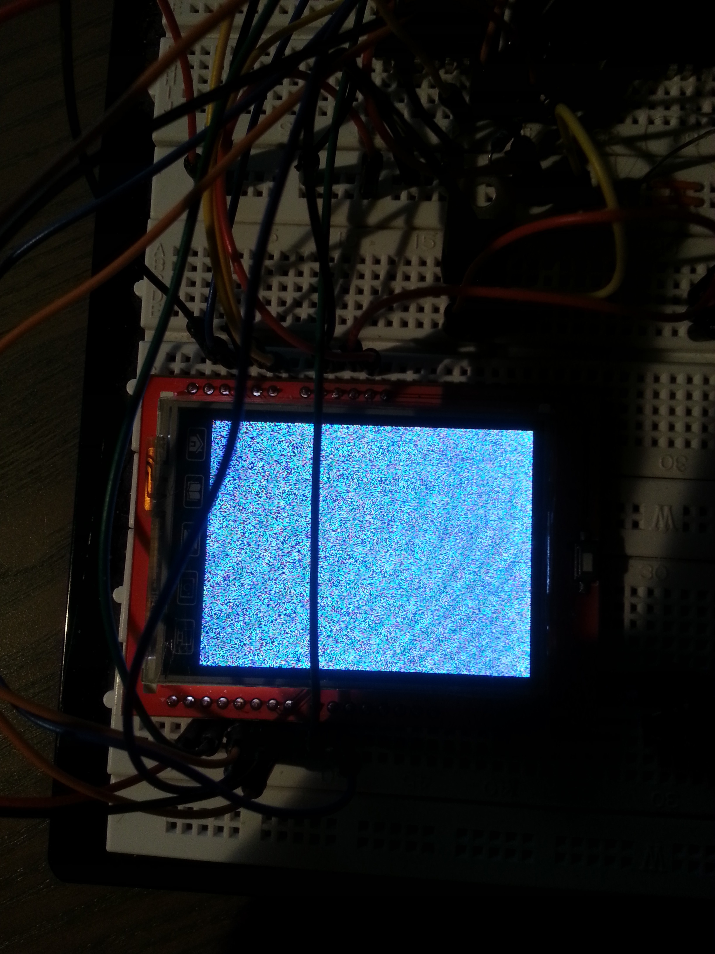
The display starts white and changes to colorfull and flickers. It's not red as i should be.
Please help guys")
I bought this TFT: **broken link removed**
I think it uses the ILI9325.
Here I found some code to use this display with an atmega32:
https://translate.google.com/transl...t_shield_2_4_atmega32/0-77&edit-text=&act=url
I'am using an AtMega1284p at 16Mhz.
The initialization-routine:
Code:
void LCD_ILI9325_Init(void)
{
    unsigned char i;
    unsigned int f;

	LCD_DATA_OUT;
	LCD_DATA_PORT = 0xFF;
	LCD_CLT_DDR = 0xFF;
	LCD_CS_H;
	LCD_RS_H;
	LCD_WR_H;
	LCD_RD_H;
	LCD_REST_H;

	_delay_ms(50);
	LCD_REST_L;  //??
    _delay_ms(50);
	LCD_REST_H;
    _delay_ms(50);


	LCD_WriteReg(0x0001,0x0000);//çåðêàëüíî âåðòèêàëü (0x0100)
 	LCD_WriteReg(0x0002,0x0700);
 	LCD_WriteReg(0x0003,0x1030);//ïðåîáðàçîâàíèÿ RGB â GBR, ñòðî÷íîé ðàçâåðòêè


 	LCD_WriteReg(0x0004,0x0000);//çåðêàëüíî âåðòèêàëü (0x0000)
 	LCD_WriteReg(0x0008,0x0207);
 	LCD_WriteReg(0x0009,0x0000);
 	LCD_WriteReg(0x000A,0x0000);
 	LCD_WriteReg(0x000C,0x0000);
 	LCD_WriteReg(0x000D,0x0000);
 	LCD_WriteReg(0x000F,0x0000);

	//power on sequence VGHVGL
	//Ïèòàíèÿ íà ïîñëåäîâàòåëüíîñòè VGHVGL
 	LCD_WriteReg(0x0010,0x0000);
 	LCD_WriteReg(0x0011,0x0007);
 	LCD_WriteReg(0x0012,0x0000);
 	LCD_WriteReg(0x0013,0x0000);

	//vgh
 	LCD_WriteReg(0x0010,0x1290);
 	LCD_WriteReg(0x0011,0x0227);

 	//vregiout
 	LCD_WriteReg(0x0012,0x001d);//0x001b

 	//vom amplitude
    // Ïî àìïëèòóäå
 	LCD_WriteReg(0x0013,0x1500);

 	//vom H
 	LCD_WriteReg(0x0029,0x0018);
 	LCD_WriteReg(0x002B,0x000D);

	//gamma
    // Äèàïàçîí
 	LCD_WriteReg(0x0030,0x0004);
 	LCD_WriteReg(0x0031,0x0307);
 	LCD_WriteReg(0x0032,0x0002);//0006
 	LCD_WriteReg(0x0035,0x0206);
 	LCD_WriteReg(0x0036,0x0408);
 	LCD_WriteReg(0x0037,0x0507);
 	LCD_WriteReg(0x0038,0x0204);//0200
 	LCD_WriteReg(0x0039,0x0707);
 	LCD_WriteReg(0x003C,0x0405);//0504
 	LCD_WriteReg(0x003D,0x0F02);

 	//ram
 	LCD_WriteReg(0x0050,0x0000);
 	LCD_WriteReg(0x0051,0x00EF);
 	LCD_WriteReg(0x0052,0x0000);
 	LCD_WriteReg(0x0053,0x013F);
 	LCD_WriteReg(0x0060,0x2700);//çåðêàëüíî ãîðèçîíòàëü (0xA700)
 	LCD_WriteReg(0x0061,0x0001);
 	LCD_WriteReg(0x006A,0x0000);

 	//
 	LCD_WriteReg(0x0080,0x0000);
 	LCD_WriteReg(0x0081,0x0000);
 	LCD_WriteReg(0x0082,0x0000);
 	LCD_WriteReg(0x0083,0x0000);
 	LCD_WriteReg(0x0084,0x0000);
 	LCD_WriteReg(0x0085,0x0000);

 	//
 	LCD_WriteReg(0x0090,0x0010);
 	LCD_WriteReg(0x0092,0x0600);
 	LCD_WriteReg(0x0093,0x0003);
 	LCD_WriteReg(0x0095,0x0110);
 	LCD_WriteReg(0x0097,0x0000);
 	LCD_WriteReg(0x0098,0x0000);
 	LCD_WriteReg(0x0007,0x0133);


    LCD_WriteComand(0x0022);//Start to write to display RAM

    //paint screen red
    for(i=0;i<2;i++)
    {
        for(f=0;f<38400;f++)
        {
            LCD_WriteData(RED);
        }
    }
}
The display starts white and changes to colorfull and flickers. It's not red as i should be.
Please help guys