Continue to Site

Welcome to EDAboard.com

Welcome to our site! EDAboard.com is an international Electronics Discussion Forum focused on EDA software, circuits, schematics, books, theory, papers, asic, pld, 8051, DSP, Network, RF, Analog Design, PCB, Service Manuals... and a whole lot more! To participate you need to register. Registration is free. Click here to register now.

Need help with replicating a circuit

Status
Not open for further replies.

DPluss

Junior Member level 2
Joined
Mar 2, 2016
Messages
24
Helped
0
Reputation
0
Reaction score
0
Trophy points
1
Activity points
230
Hey All!

I'm a real beginner in electronics but as a car mechanic I face it every day.

Let me explain my problem, I have a small circuit which I bought on the internet and I would like to replicate it since it kinda melted over the year I used it!

This little "device" connects the 5W parking light of my car to the 21W signal light so it works like a side-marker in the US, when my 5W parking light is on, my indicator light is illuminated with 5W aswell which is not so bright but its because when I use my signal light it gets its full 21W.

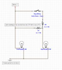
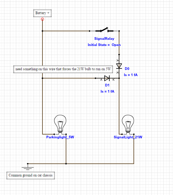
I figured out that it uses 2 diodes, 1 for the + of the parking light so it doesnt signal when using the signal, and one for the + of the signal to prevent the parking light from turning on the signal light on the back of the car. What I dont know is how do I make a 21W bulb to work on 5W?

The circuit would look like this if I exlude the thing that converts the 21W to 5W:

 
Last edited by a moderator:

So a light bulbs power rating is simply a roundabout way of giving you the coil resistance. It tells you how much power the bulb will dissipate when you apply the voltage they expect you to apply, in this case 12V(?) from the car battery. Nothing is stopping you from dissipating more or less current through the bulb, other than maybe the point at which the filament breaks. I'm guessing the mysterious component is some kind of regulator that lowers the voltage that you apply to the signal light thus lowering the current and power through the bulb.

When the relay is connected the vertical diode will conduct and the horizontal diode will not and you'll get the full battery voltage across the bulb. Do you have a picture of the device you're talking about?
 

The circuit looks like this, the white thing is the "regulator"

fnPYtya.jpg

I used a multimeter and it almost halves the voltage, so the bulb gets about 6v, I dont really know what kind of resistor is it....
 
Last edited by a moderator:

The "white thing" with two legs is nothing but a power resistor in my opinion. From the size of it, it is approx 5W.
 
  • Like
Reactions: DPluss

    DPluss

    Points: 2
    Helpful Answer Positive Rating
The "white thing" with two legs is nothing but a power resistor in my opinion. From the size of it, it is approx 5W.

I looked up in google, I found this:

Vitrohm_12k.JPG

It has the same logo as the one I have, sadly the text on mine is burned...

Since you said its approx 5W, how does one mesaure this power resistor to know the exact W?
 
Last edited by a moderator:

The "white thing" with two legs is nothing but a power resistor in my opinion. From the size of it, it is approx 5W.

That is what I suspected. If it halves the voltage, then it is working in spite of the burned circuit board. If you want to make more of them, test that power resistor with an ohm meter. You can get them at Digikey for less than $1.00 each. 10 watt power resistors would last longer.

- - - Updated - - -

The wattage of the resistor just determines how much power it can handle.
The resistance (in ohms) is what determines how bright your light will be.
 
Last edited:

That is what I suspected. If it halves the voltage, then it is working in spite of the burned circuit board. If you want to make more of them, test that power resistor with an ohm meter. You can get them at Digikey for less than $1.00 each. 10 watt power resistors would last longer.

- - - Updated - - -

The wattage of the resistor just determines how much power it can handle.
The resistance is what determines how bright your light will be.

Thank you very much for all your help!

I will try a 5.1ohm 10W resistor for my new one with 2x 3amp diodes!

I'll let you guys know the results! :)
 

sadly the text on mine is burned...

Usually the ink used for marking all electronic components are very stable (does not burn). To remove the marking, one uses erasers containing glass fiber that basically sand-papers the marking.

If you use some organic solvent and wipe with a cotton swab, perhaps you will still be able to read it...
 

Status
Not open for further replies.

Part and Inventory Search

Welcome to EDABoard.com

Sponsor

Back
Top