Continue to Site

Welcome to EDAboard.com

Welcome to our site! EDAboard.com is an international Electronics Discussion Forum focused on EDA software, circuits, schematics, books, theory, papers, asic, pld, 8051, DSP, Network, RF, Analog Design, PCB, Service Manuals... and a whole lot more! To participate you need to register. Registration is free. Click here to register now.

[PIC] Power factor measurement using PIC18f4520

Status
Not open for further replies.
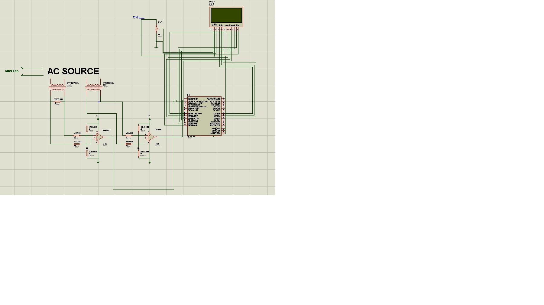
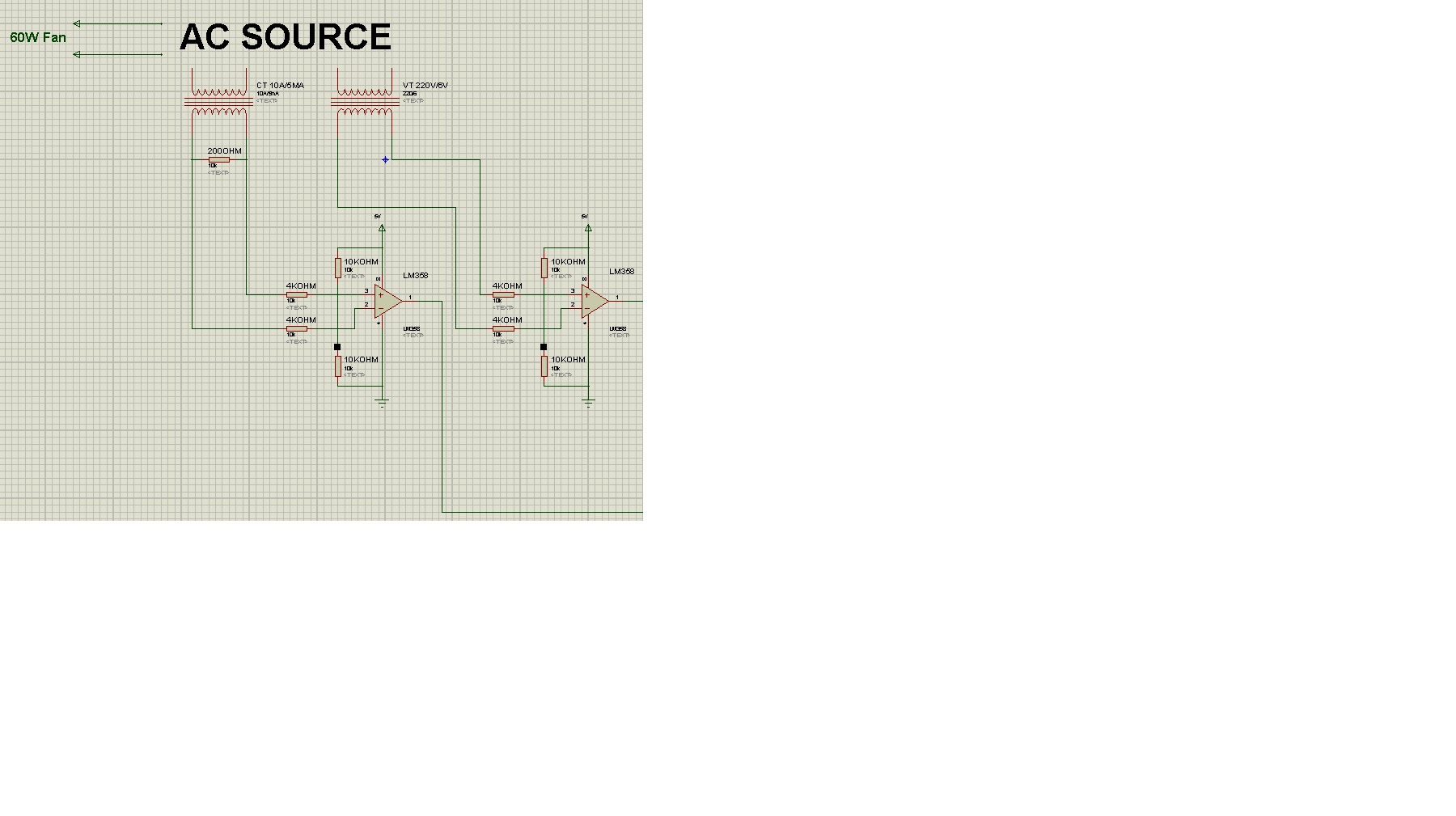
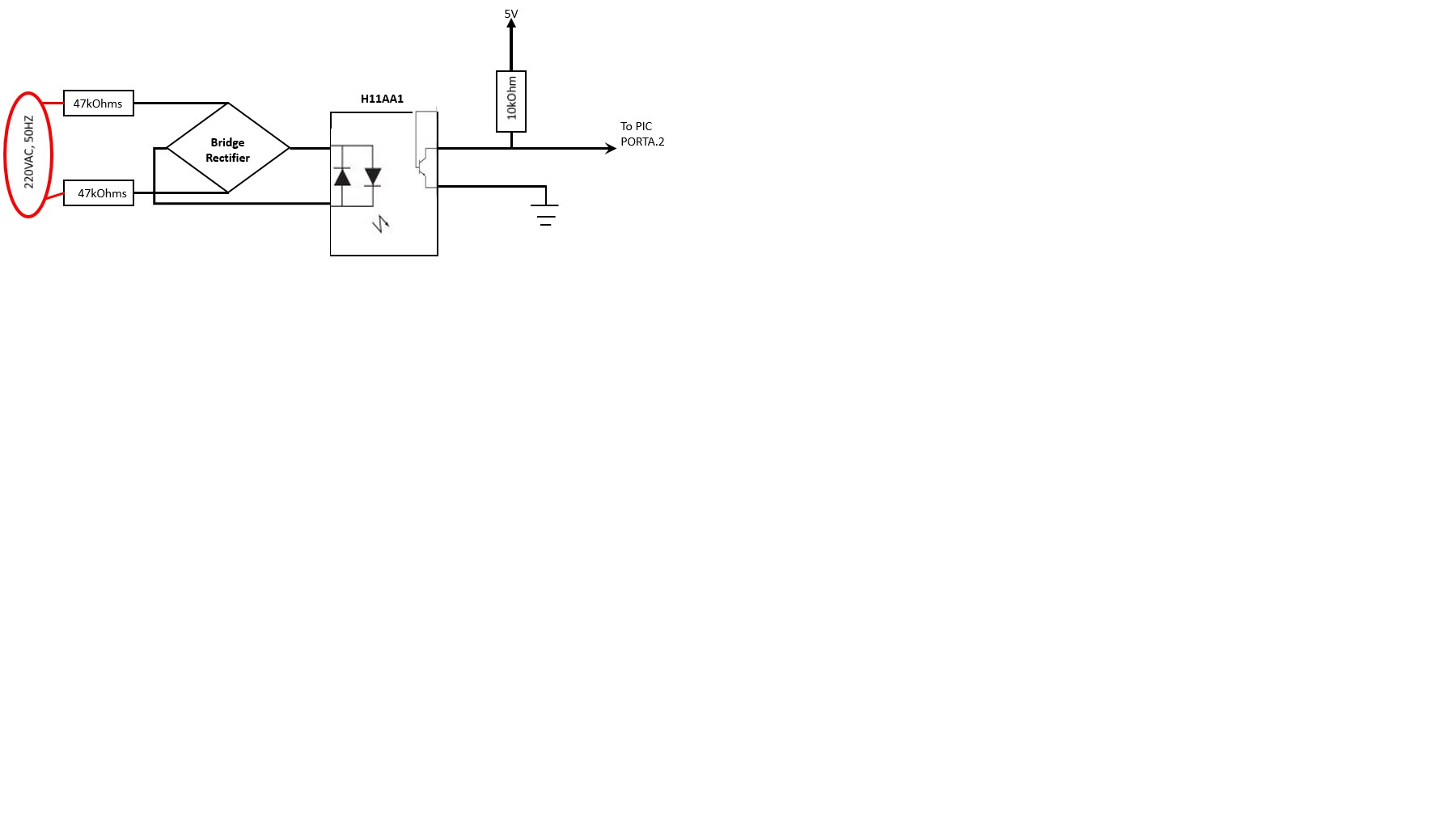
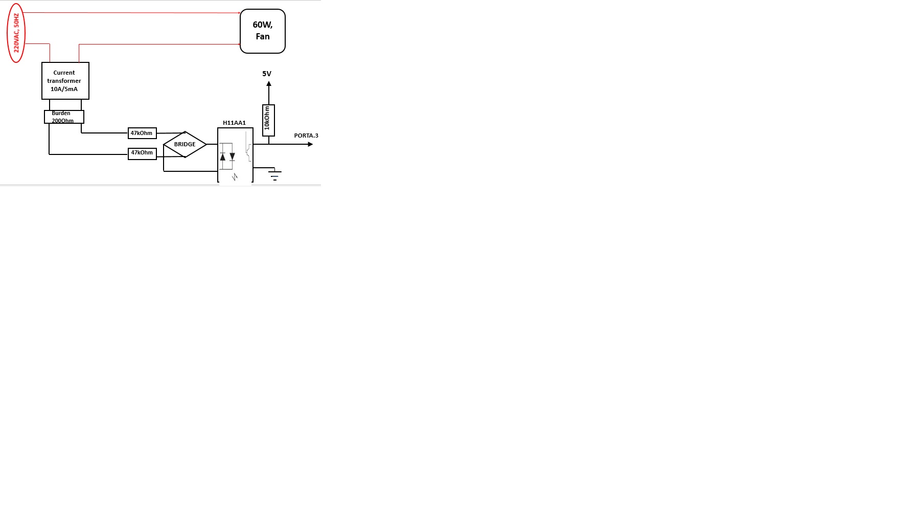
For the CT circuit, its link is previously posted, of 10A/5mA has 4 legs, two for input two for output.

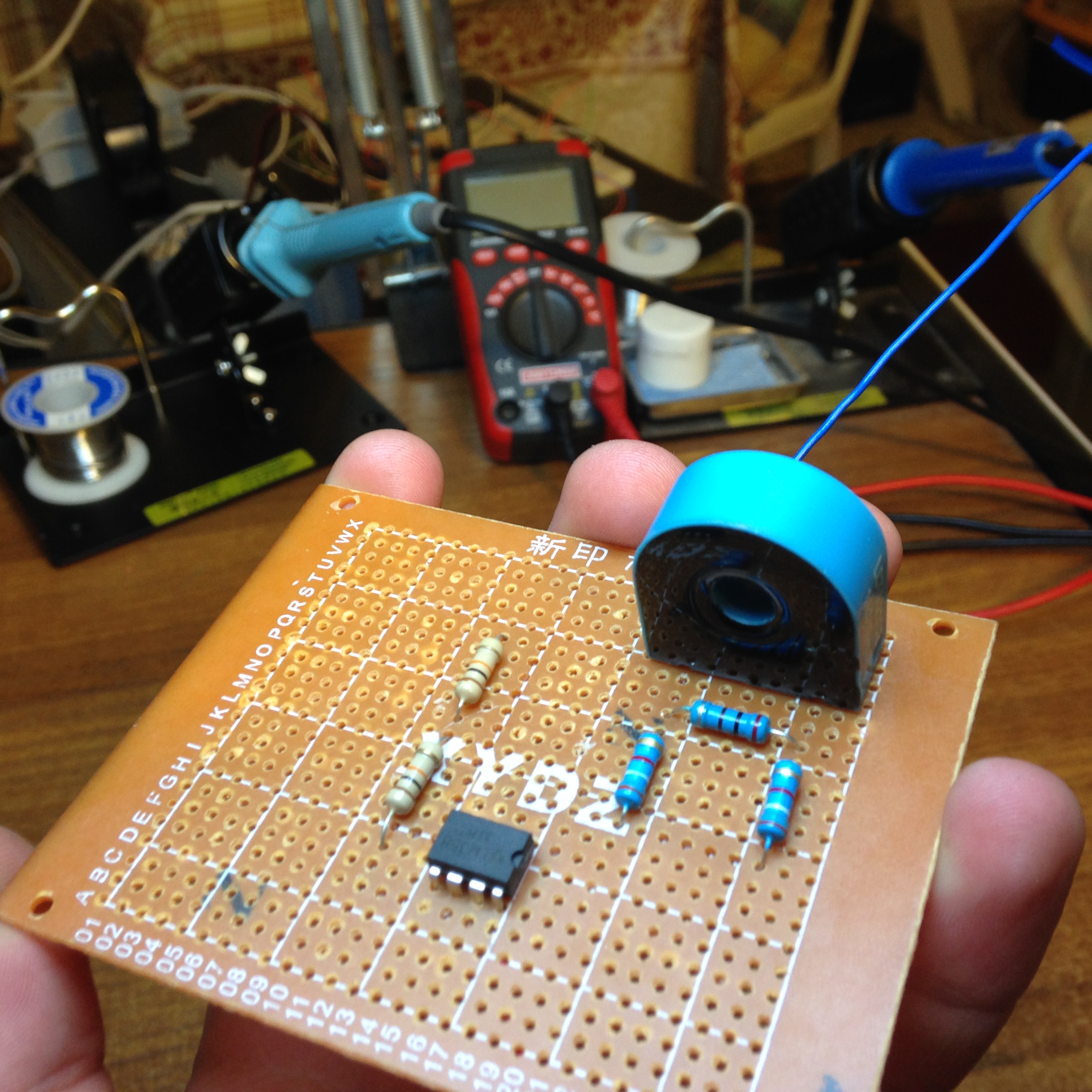
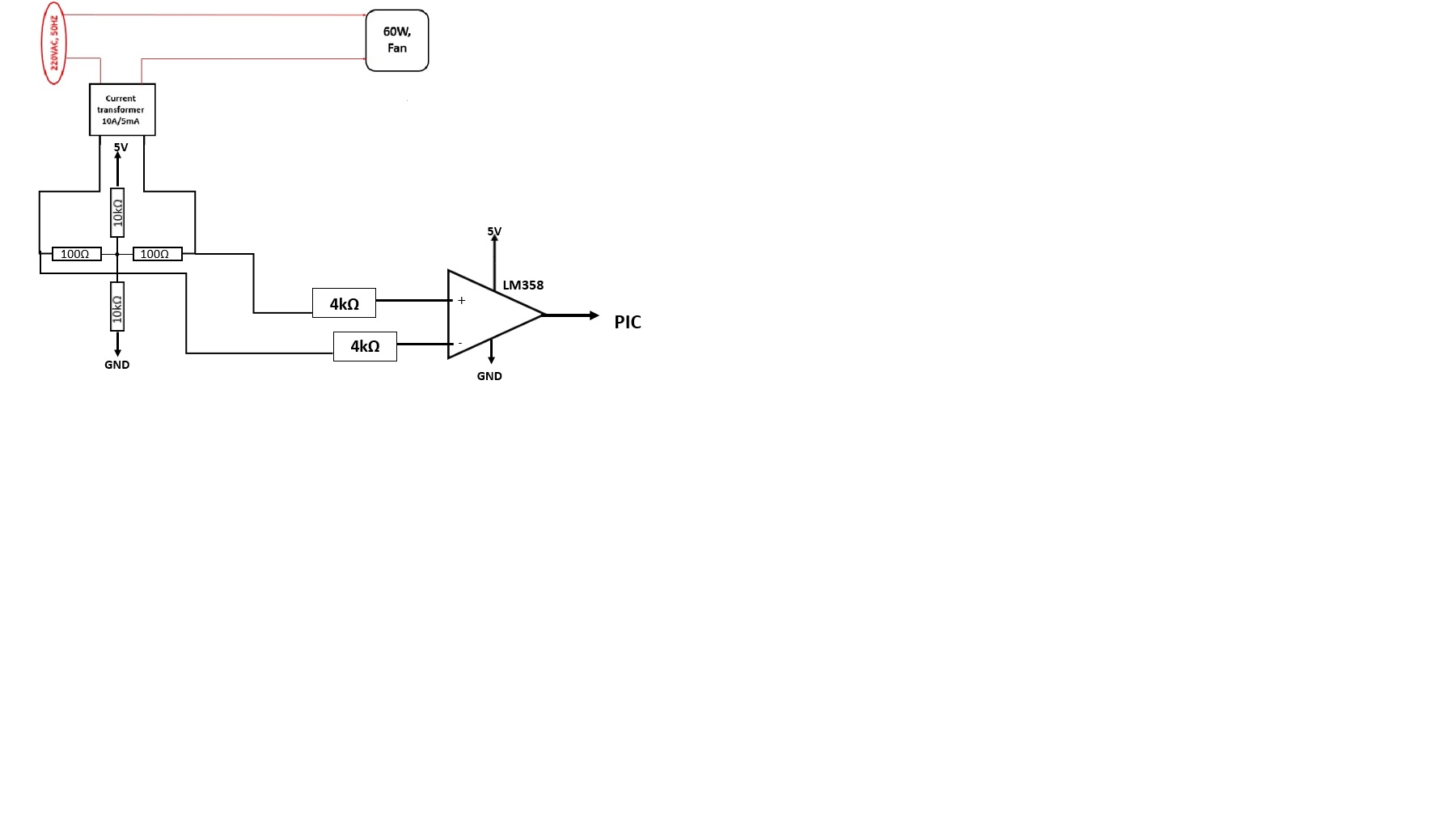
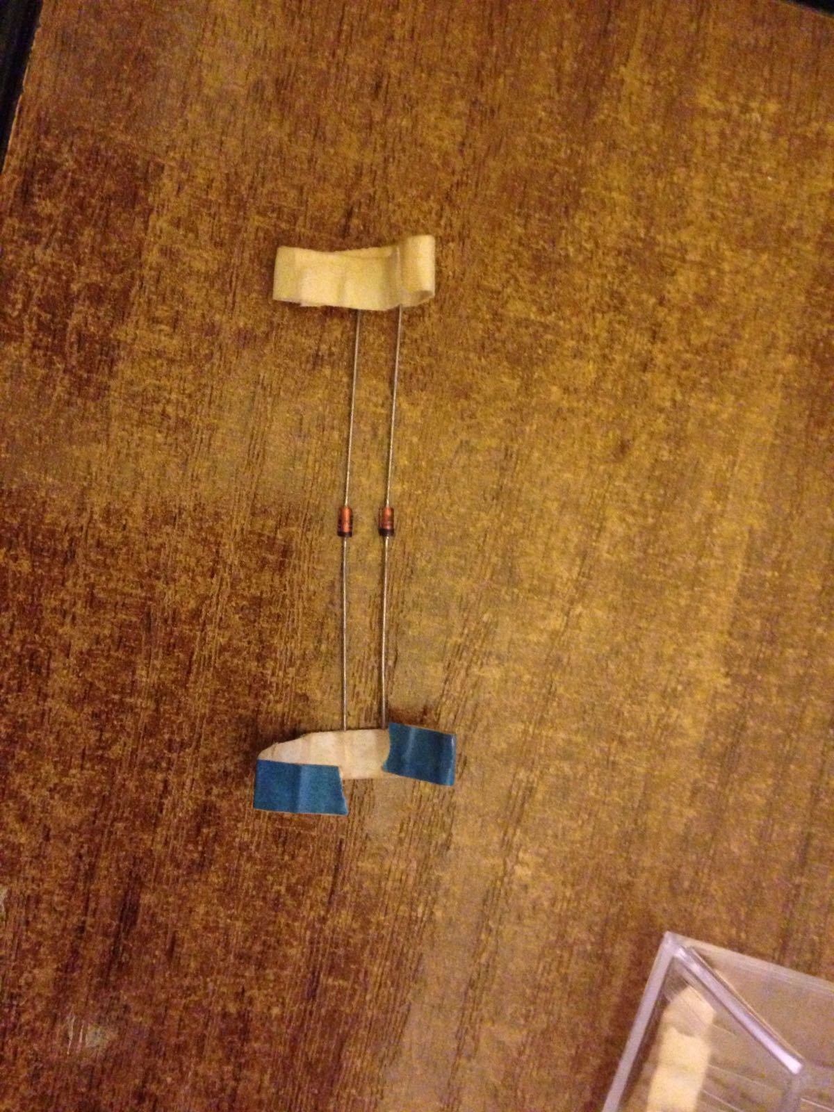
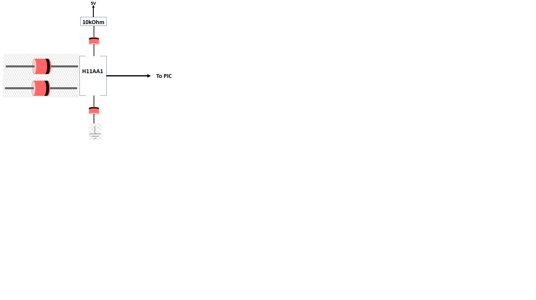
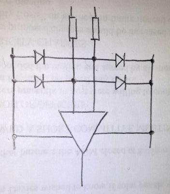
We have agreed to shunt a 200 ohm resistors to its output legs, then enter it to comparator biased circuit same as VT one; the problem is, even in its datasheet no statings were found to define the input from output terminals, so using a DVM, i made a resistivity check for both two sides: on the front two legs, the resistance was too high (O.L) on the rear two legs, the resistance was of 150 ohms, doens't this mean that the front legs must be connected in series with the fan, and the rear legs must be shunted with the burden and connected to LM358 circuit?

Something does not look right. For the current transformer, the input side should be having a very low resistance because that will take a high current. The resistance should be less than 1R because at 10A it will dissipate 100W. The output side (secondary side) resistance will be of the order of 10-100R (can be even 1K) because it will be loaded with a resistor to convert the current into a voltage. If one winding is showing very high resistance (OL), the winding is perhaps open. Can you please post a picture of the CT you are using?

- - - Updated - - -

I think you need to pass the current carrying conductor through the hole in the transformer and use the output from the winding showing 150R. Leave the two legs without continuity open.

Here it is:

**broken link removed**

- - - Updated - - -

Here it is:

**broken link removed**

The 200ohm resistor is connected to the side showing 200 ohm right?

From other part, if such transformer uses the effect of magnetic field to reproduce an image of the current passing, what is the purpose of the other very high resistance legs?
 

I saw the datasheet (the pdf icon) and what I suspected is right. The main current carrying conductor goes through the hole and the recommended load is 200R. Two legs are dummy (meant for physical support). Please look up the datasheet. They recommend an opamp in the datasheet.
 
Hello,

For the CT connection, here is its circuit soldered:


In the circuit above, an 200ohm burden is used, with same bias resistors of VT circuit (10kOhms)

My load is a big fan (used for cooling) of 60W.


The following is a complete image of the total circuit:


Here is a focused image on the ZCD circuit:


In real world circuit, I've connected the diagram as shown on Proteus: the circuit went totally ok, no faults have occurred and I haven't been shocked till death or been killed.

I wanted to test the time between the current crossing zero, and current crossing zero, in order to assume the displacement power factor, here is the code via PIC18 IDE Simulator:

Code:
ASM:        org 0x800
Define LCD_LINES = 4
Define LCD_CHARS = 16
Define LCD_BITS = 8  'allowed values are 4 and 8 - the number of data interface lines
Define LCD_DREG = PORTB
Define LCD_DBIT = 0  '0 or 4 for 4-bit interface, ignored for 8-bit interface
Define LCD_RSREG = PORTD
Define LCD_RSBIT = 0
Define LCD_EREG = PORTD
Define LCD_EBIT = 2
Define LCD_RWREG = PORTD  'set to 0 if not used, 0 is default
Define LCD_RWBIT = 1  'set to 0 if not used, 0 is default
Define LCD_COMMANDUS = 2000  'delay after LCDCMDOUT, default value is 5000
Define LCD_DATAUS = 100  'delay after LCDOUT, default value is 100
Define LCD_INITMS = 100  'delay used by LCDINIT, default value is 100
'the last three Define directives set the values suitable for simulation; they should be omitted for a real device
Lcdinit 0  'initialize LCD module; cursor is blinking

Dim volt As Word
Dim current As Word
Dim x As Single
Dim timer As Word
timer = 0

main:

WaitMs 800
Lcdcmdout LcdClear
Adcin 2, current
Adcin 1, volt
Lcdout "", #volt
Lcdcmdout LcdLine2Home
Lcdout "", #current
start:
	If current = 0 Then
		timer = timer + 1
		If volt = 0 Then
			Goto stop
		Else
			Goto start
		Endif
	Endif
stop:
	Lcdcmdout LcdLine3Home
		Lcdout "T = ", #timer
	WaitMs 800
	
Goto main
End

The CT circuit is able to detect zero, and send it to display, but unfortunately the VT circuit wasn't able to detect any zero crossings; I've changed to bias resistors of its LM358 circuit, from 10K to 1K, but still no zero was detected from VT circuit.

Example of how LCD shows a zero value for current but no zero value for voltage:


The code must definitely must be modified in order to set a correct timer, and make assumptions for angle phi, are the resistors for VT circuit must also be modified?

Thanks in advance
 

The results are not accurate, and I'm still not sure if elements must be added/modified from within the circuit to correct this issue, or is it a pure programming process.

How to build code for an exact timer using PIC18 IDE and how can this timer be converted into real world time?

What relation is there between timer and phase angle, is it based upon assumptions and rule table calculations?
 

I think you may have a hardware problem and possibly software as well.

The ZCD circuits may well have overloaded inputs, particularly the voltage detector. This could lead to latch-up or even damage to the LM358s.

A 6V RMS transformer with little load is probably producing aound 7V (the rated voltage is specified under load) so peak to peak it will reach (2 * SQRT(2) * 7) ~20V. That is within the maximum differential range of the LM358 but the absolute input voltage should not exceed the supply voltage (ON Semi data sheet, page 3). The resistors in series with the inputs will help to protect the IC but such excesive voltages applied across the inputs probably causes them to alternately clamp and measure on each half cycle. This may still work but I would be concerned about long term reliability.

You will get more consistent results if you further reduce the voltage from the 6V transformer, possibly clamping it so it stays within ground/5V levels. Even better is to remove the transformer completely and use an opto-coupler. It would be smaller, still give isolation and the output would already be at logic levels and maybe give better noise immunity. Remember that a fixed phase shift in the voltage sensor is not important because that will be your reference 'zero' anyway, what is important is that the reference is stable or the timing will be inaccurate.

The phase angle is simply a measure of the time delay between voltage and current zero crossings, presented as a proportion of one cycle. It can be mathematically calculated once you know the exact AC frequency, tables are not needed.

For highest precision, you want a hardware timer to reset at voltage zero crossing and reach it's maximum count (255, 65535...) at the end of one AC cycle. That means that if you stop the timer as the current passes zero, it will hold the most accurate measurment of elapsed time. Take into consideration the AC frequency when working out the timer counting rate, for example tdo you have to cater for 50Hz or 60Hz AC and if it will be used on a generator supply, should it be able to work if the engine is slightly over or under speed. I would recommend you use either TMR1 in TMR3 in this application.

Which compiler are you using to write your code?

Brian.
 
Why don't you try two antiparallel zener diodes, about 3V, put at the input of the comparator for the V detector circuit?
 
Why don't you try two antiparallel zener diodes, about 3V, put at the input of the comparator for the V detector circuit?

Could you please post a schematic?

- - - Updated - - -

I think you may have a hardware problem and possibly software as well.

The ZCD circuits may well have overloaded inputs, particularly the voltage detector. This could lead to latch-up or even damage to the LM358s.

A 6V RMS transformer with little load is probably producing aound 7V (the rated voltage is specified under load) so peak to peak it will reach (2 * SQRT(2) * 7) ~20V. That is within the maximum differential range of the LM358 but the absolute input voltage should not exceed the supply voltage (ON Semi data sheet, page 3). The resistors in series with the inputs will help to protect the IC but such excesive voltages applied across the inputs probably causes them to alternately clamp and measure on each half cycle. This may still work but I would be concerned about long term reliability.

You will get more consistent results if you further reduce the voltage from the 6V transformer, possibly clamping it so it stays within ground/5V levels. Even better is to remove the transformer completely and use an opto-coupler. It would be smaller, still give isolation and the output would already be at logic levels and maybe give better noise immunity. Remember that a fixed phase shift in the voltage sensor is not important because that will be your reference 'zero' anyway, what is important is that the reference is stable or the timing will be inaccurate.

The phase angle is simply a measure of the time delay between voltage and current zero crossings, presented as a proportion of one cycle. It can be mathematically calculated once you know the exact AC frequency, tables are not needed.

For highest precision, you want a hardware timer to reset at voltage zero crossing and reach it's maximum count (255, 65535...) at the end of one AC cycle. That means that if you stop the timer as the current passes zero, it will hold the most accurate measurment of elapsed time. Take into consideration the AC frequency when working out the timer counting rate, for example tdo you have to cater for 50Hz or 60Hz AC and if it will be used on a generator supply, should it be able to work if the engine is slightly over or under speed. I would recommend you use either TMR1 in TMR3 in this application.

Which compiler are you using to write your code?

Brian.

Thanks for replying.

You've provided vast explanations, as if I am reading multi Wikipedia articles ;p

Before making a summary, please note that the mains are of 190VAC not 220VAC.

-----

If I replace the 220/6VAC transformer with a 220/5VAC you think that the overload at the inputs of LM358 would vanish? Is that an efficient quick treatment for the circuit? [[If I use a series voltage divider, in case I don't want to buy another transformer, from 6V to 5V, would that be also a problem?]]

What about ZCD with CT: do you have any concerns about it? Would it efficiently last, with no undesired effects?

----

About the opto-coupler, I've never used such a device in any circuit, is there any specific datasheet name so I can read a little bit about it to know how to branch it, and how does it work?

----

I`m using PIC18 IDE Simulator from OshonSoft.

Assuming the transformer is replaced with maximum output of 5V [Regardless of external hardware timer circuit, and regardless of usage of an opto-coupler], and assuming you have no restricts about ZCD with CT, how to build a timer in the compiler that serves the following:

when PORTA.2 equals to zero (zero crossing detection of current) start timer, until PORTA.3 equals to zero (zero crossing detection of voltage).

then apply a certain formulae to determine the phase angle and thereby the power factor.
 
Last edited:

Hello,

If the ZCD with voltage transformer, (even if modified to 220/5VAC) is good enough for long term usage, here is what I've found based on an RC filtering circuit, at the output of the opamp:


In the above image the opamp used is 741, but can work for LM358.

If the choice of any transformer is not advised, here is what I've found based on opto-coupler H11AA1 devices, to detect zero crossings:


In the above image, the circuit gives a peak of 5V whenever a zero crossing occurs as follows:


Accordingly, I can time the delay between current crossing zero, and voltage crossing zero whenever a HIGH logic is observed at the analogue input pin of the PIC18F4520.

Still, the following is an opto-coupler, edge detection circuit, but this time using another type of opto-coupler 4N25:


This whole analysis, is done after taking into consideration that the ZCD Current transformer is O.K and do not have any hardware problem.

Please state if the ZCD for voltage circuit, can be done by decreasing the output of the potential transformer from 6VAC to 5VAC, or must be done with an opto-coupler as shown above.

Thanks
 

You can do it many ways. All of the above are valid methods but I would suggest there is a better way of using the optocoupler that avoids the high power rated resistor and is also more efficient. What isn't clear is those schematics show a 24V AC input but I'm guessing you really have 220V AC and they do not show how the voltage is dropped to 24V. If you use a reactive circuit, for example another transformer, it will introduce a phase shift of it's own which only complicated things further.

I suggest you do it this way:
Connect the 220V AC input to two 47K 0.5W resistors, one in each wire (for safety, they are electrically in series anyway) then to a bridge rectifier with it's output wired to the LED side of the optocoupler. So its similar to the final schematic in your last post but the bridge rectifier is on the LED side of the resistors. By moving the bridge you no longer have to use high voltage diodes, you can use small signal diodes (1N4148 for example) because the LED clamps the voltage across them to no more than about 2V.

The optocoupler method has almost zero phase shift and is entirely voltage operated so it gives a good reference to reset the delay counter.

Brian.

Hello and thanks for replying.

According to your professional "suggestion" here is the ZCD circuit of voltage:


As for the ZCD for current, I will use also an H11AA1, instead of LM358, by taking into consideration update experience about burden resistor, and loop hole which carries one conductor, with the following connection:


If both ZCD for V and I are O.K and approved I will solder them, then talk about how to code for timer in PIC18 IDE Simulator.

Thanks
 

I see a problem. The H11AA1 has bi-directional LEDs, you can either use a single LED opto-coupler like the 4N25 or you can still use a H11AA1 but leave the bridge rectifier out and just connect the resistors directly to the opto-coupler. The bridge is there to rectify the AC so it produces DC to drive the LED but the H11AA1 works with both polarities so you may as well drive it directly with AC.

The opto-coupler will not work with the current measurement I'm afraid. The voltage across the secondary of the CT is too low and if you removed the resistors, even if there was enough voltage, the LEDs would clamp it and probably distort the waveform. I would go back to the op-amp for current monitoring but maybe bias it's inputs slightly differently. I'm thinking to connect the CT secondary differently. If the burden shuld be 200 Ohms, make it from two 100 Ohm resistors in series and from their junction, wire a 10K resistor to +5V and another one to ground. That makes the circuit symetrical and the op-amp inputs sit at 2.5V when no current is being drawn. It should give highest sensitivity that way but you will have to be careful to ignore random noise pick-up.

Brian.
 
Hello and thank you

I've branched the circuit just like you said, using H11AA1, with no bridge rectifier, whereas the 220VAC input lines are each series connected with 47kOhms, and entered to pins 1 and 2 of H11AA1.

The emitter of the transistor (pin4) is connected to the ground of the DC 5volts.

The collecter of the transistor inside the optocoupler, is connected to a 10kOhms resistor, then to +5VDC.

I've placed a DVM on the node where it must be headed to porta pin (in the schematic where its written PORTA.2), and the other terminal of circuit ground.

When I feed this circuit with the 220VAC mains, I see a value of 1.173VAC on the DVM screen, and 0.872VDC.

When mains are not connected I see a 5VDC on DVM and 0VAC.

Is this voltage ZCD is working properly?

Much thanks in advance
 

You really need an oscilloscope to see the waveform but from those readings it is likely to be working properly. The output of the optocoupler will be very short pulses at twice AC line frequency (remember the waveform crosses zero twice per cycle). A DVM on a DC range will not have time to sample the voltage so the reading will be wrong, similarly on the AC range it will be calibrated for a sine waveform so with pulses the reading will be wrong. The fact that there is a reading other than 5V means there is signal present so it is probably good.

I would like to make a suggstion that makes the software easier: connect the ZCD signals to RB0, RB1 or RB2 on the PIC. The reason I suggest this is because those three pins can be used as interrupt inputs. Ideally, you want to start and stop the timer as rapidly as possible when the zero crossing is detected. If you use the polling method (reading the pins in sequence) there will inevitably be some additional delay as the software steps through the code to the instruction that reads the pin state. If you use interrupts you can get a faster response because the ZCD signal itself can trigger the timer routines in hardware rather than software. It is up to you, the inaccuracy with the polling method is small if you are using a fast clock speed anyway.

Brian.

Yes, thanks.

Before connecting the two output of ZCD circuits, is the following current ZCD circuit is O.K:


If you don't see any problem, you were saying that its output, as well as the output of voltage ZCD must be connected to two first pins of PORTB >> How to set a timer using PIC18 IDE Simulator, such that when PORTB.1 is high (have an input of 5V, considered to be obtained from ZCD at the zero cross moment) and stop this same timer when PORTB.2 is high (corresponding to other quantity ZCD)


Thanks
 

You don't have to use PORTB but it will give the most accurate measurement.

The program flow is like this:
1. configure the timer so it counts internal clock cycles.
2. turn the timer off so it doesn't count by itself.
3. zero the timer so you have a known starting value.
4. configure the PIC so RB0 and RB1 are interrupt inputs.
5. write an interrupt service routine (ISR) that gets called when RB0 or RB1 have a signal on them.
6. if the interrupt came from RB0, turn the timer on. (voltage ZCD)
7. if the interrupt came from RB1, turn the timer off. (current ZCD)

The value in the timer is then proportional to the delay between the two zero crossings. From that value and how fast the timer was counting, you can calculate the elapsed time and therefore the phase angle between the signals.

Your current ZCD circuit is good. If you want to add extra protection in case of high current spikes (they will translate to high voltage spikes from the CT) you can do it easily with 4 small signal diodes. Wire two to each input pin at the LM358, one diode to ground with it's cathode to the IC, the other to +5V with it's anode to the IC. They will not do anything at all in normal operation because they are reverse biased but if the voltage tries to go below ground or above 5V they will conduct and clamp it to a safe level.

Brian.

Thank you Brian!

Before posting how the safety circuit of CT would look alike, is this what you refer to as "small signal diode":


If yes, the sub-circuit focusing only on H11AA1 terminals would look like:


As for the software part:

I've read about "What is an Interrupt" and saw that the pins that could be used for that purpose are as you previously stated, PORTB0,1,2.

I`m writing the code, via PIC18 IDE Simulator. I understand the flowchart you gave, and it is very simply to understand and reasonable. I`ve look forward in the BASIC Compiler Reference Manual, and read about Using interrupts explanations, and in the part of Defining clock signal I didn't come up of how to set PORTB pins 0,1,2 (need only two of them) to function as interrupt pins; should it be coding using assembly and writing ASM before it?

As for counting internal clock cycles, in the references it is only stated about the value of the clock cycles to be used; how to set an order such within the code tells the PIC to count internally?

Could you please post about ISR routines to be written?


Much thanks
 

No, that's not quite right.

The voltage detection is done with the opto-coupler and the two resistors. It is inherently protected because the LEDs inside the opto-coupler are constant voltage devices, it means the voltage across them can not go above their rated Vf (~1.2V) and any excess voltage will be turned into heat in the resistors. So you do not need to protect the opto-coupler circuit.

That isn't true of the LM358 though. If the voltage at it's input pins is allowed to go higher than its supply voltage or go below the ground potential (=negative in your circuit) it might damage the IC. If you wire the diodes as in my diagram it should protect the IC.

(sorry if the image is rotated in your browser, Edaboard sometimes does that)

The diodes are wired so they never normally conduct so they will have no effect on the zero crossing waveform. If the voltage goes too high or too low, one of the diodes will start to conduct and safely 'dump' the excess power to ground or the supply line. The reason I suggest protection on the current monitoring circuit is that the secondary voltage in the CT is proportional to the current in the primary (the power wire passing through it). With the 60W fan as load there would be no problem but if you accidentally put a heavier load or a short circuit on it, the secondary voltage would be much higher.

I often find people are frightened of using interrupts but they are incredibly useful things. The only difference between a 'normal' subroutine and an ISR is that a subroutine is called from within the software and an ISR is called in response to a hardware condition. In practical terms, that means the ISR may be called at any time because the program may be unaware of what is happening in the world around it and therefore there has to be a method of remembering what the program was doing so it can return to it after the interrupt has been dealt with.

The classic example is you are watching a DVD and your phone rings. You press the pause button on the DVD player, answer the call then cancel the pause and carry on watching the movie. In the example, the movie is the main program and the phone call is the interrupt. When you press pause you are saving the place in the movie so you can return to it when you have finished your conversation.

In PIC software an ISR first saves some of the critical registers so they can be used within the ISR. At the end of the ISR, the contents of those registers is restored and the routine finishes. The main program then continues without knowing the interrupt ever happened.

I will have to have to read the documentation on how Oshonsoft do it. I have a copy of all their compilers but I normally program in C or assembler so I'm 'rusty' at BASIC !

Yes, those are the kind of diode I meant.

Brian.


Thank you Brian!!

Things are now more clear, and everything is O.K concerning the hardware.

Since the LCD data 8-bits pins are all connected to PORTB pins, is it possible to connected the output signals of ZCD of V/I to PORTA, and make ADC, with a manual timer (using also BASIC), just to see test results?

According to your explanations about "interrupt", and since it would consume much time for a first time ISR writing, let's give a try to make it as a normal subroutine, and I will give it main only importance as if I am only waiting for the phone call (in the classic example) , in a way that no instructions would be coded to the PIC before knowing time between phase shift, even LCD writing codes.

Awaiting your acknowledgments
Much thanks & appreciations
 

Khaled;
what you are proposing is called "polling".

Using Brian's example, this is similar to a person that is making several chores around the home:
1) you are preparing food in the kitchen,
2) you go outside and water the trees,
3) go to check the baby in its room to see if it is sleeping, and
4) then you go to the room where the phone is located to see if it is ringing......always in that order.

Every task takes some fixed time, and because you are doing them sequentially, they each have to wait the turn.

Now imagine............. that you have just walked into the kitchen and the phone rings. You ignore it and continue working in the kitchen. Then you still ignore it and go water the trees outside, then you go and watch the baby. Then and only then, you go out and check if the phone is ringing.

You know what is going to happen, right? You may be able to answer the phone, but most likely you will miss the call.

That my friend, is the purpose of interrupt routines in controllers. You will have to use one sooner or later. I strongly advise you that, as part of your learning process, learn how to use them.
 
Status
Not open for further replies.

Part and Inventory Search

Welcome to EDABoard.com

Sponsor

Back
Top