Continue to Site

Welcome to EDAboard.com

Welcome to our site! EDAboard.com is an international Electronics Discussion Forum focused on EDA software, circuits, schematics, books, theory, papers, asic, pld, 8051, DSP, Network, RF, Analog Design, PCB, Service Manuals... and a whole lot more! To participate you need to register. Registration is free. Click here to register now.

[PIC] Power factor measurement using PIC18f4520

Status
Not open for further replies.
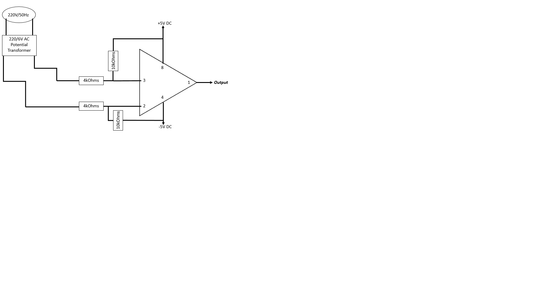
They are of little consequence, except that limit current in case of a latch-up. You can use any value from 1K to 10K (hence 4K is good value). The best accuracy is obtained when the input voltage is close to 1V. You can clamp the input voltage with a zener and work on the software.

What about the bias resistors? same conditioning? From another part, I`m worried that the VT has the following ratings: 220/6V , means that its outputs is under minor cases still bigger than 5V, wouldn't this affect maximum limitations for ADC inputs?

Still, there aren't any rectifiers, and according to KlausST it is not a problem as long as Voutmax is withing margins.
 

Hi,

Still, there aren't any rectifiers, and according to KlausST it is not a problem as long as Voutmax is withing margins.

I`m not sure what you want to achieve.
When you use the circuit above you get two square wave signals. One for current, one for voltage.
But with this configuration you can not measure "how much" current or voltage.
But you are able to measure the timing.

when you use the rectifier, then probably you never see a signal, because it never "crosses" the zero level. It comes near zero, so it depends on the OPAMP_offset_voltage if the output switches or not. It is not defined somehow.

***
timing measurement:
Think of an extreme case. You have a phase angle controlled current. Lets say with pure ohmic load.
Lets assume a phase angle of 90°
Can you imagine the waveform?
* 0° to 90°: flat line at zero
* 90° to 180°: hard rising edge to sine peak current, then it follows the sine shape down to zero.
* 180° to 270°: flat line at zero
* 270° to 360°: hard falling edge to negative sine peak current, then it follows the sine shape down to zero.

When do you expect your "zero cross" circuit to detect the crossing?
Half of the time the current is about zero. So there is no defined point.

****
Here comes the point where it depends what you want to achieve.
If you want to seperate/calaculate effective power from apparent power, then you should know that withh the given example all the power is effective power. So you should expect the zero cross at 0°.

If you want the phase shift of the distorted sine, then you should expect the zero cross near 45°.

*****
If you are interested in the true effective power... (how much energy you have to pay for)
Then i think there is no way around a true power measurement.
* no rectifier
* measure voltage with an ADC
* measure current with an ADC (both with the smallest possible time delay to avoide phase errors)
* multiply both to get the effective power.
* filter the effective power.
--> you need to adjust sampling rate and filters precisely to get reliable power values.

Klaus
 
Hello,

I've started with potential transformer with the following figure exactly:


I branched the multimeter to output pin, and its other terminal to the common GND of the circuit.

Results on the multimeter were: 1.8VAC and 2.4VDC

If I`m not able to see a zero value on the multimeter, (this is the case of all digital multimeter, where when valuing an AC parameter, it cannot display its zero crossing, since its too fast to capture [50hz]), how come the ADC input of the PIC will detect a zero value of circuit's output.

Shall I connect the output of the schematic, to PORTA.1 and make an if condition where when PORTA.1 is zero (low) then do whatever (like set a timer), to see if the functionality is good or not?

- - - Updated - - -

Hi,
I`m not sure what you want to achieve.
When you use the circuit above you get two square wave signals. One for current, one for voltage.
But with this configuration you can not measure "how much" current or voltage.
But you are able to measure the timing.
Klaus

That's the point, that whenever a zero signal is detected, starts a timer, that stops counting when another zero signal is detected from other transformer.


Using this timer, I make software calculation to determine angle phi, and accordingly get the power factor.
 

Hi,

...you don't give informations. Just new schematics and new questions. So it's hard to help.
I'll try anyway

*****
Yor new circuit has some issues:
* the output is purely on/off. No analog value. Still unclear if you want this.
* it introduces an offset, so it is impossible to switch at zero volts. Not 50% duty cycle.
* the output voltage is not compatible with your microcontroller.

*******
Doesn't the microcontroller have comparator inputs?
*******

If I`m not able to see a zero value on the multimeter, (this is the case of all digital multimeter, where when valuing an AC parameter, it cannot display its zero crossing, since its too fast to capture [50hz]), how come the ADC input of the PIC will detect a zero value of circuit's output.
This statement is too general. And I don't think it's true here.

I recommend you to use a scope instead of a DVM. It gives yo so much more information...

******
Shall I connect the output of the schematic, to PORTA.1 and make an if condition where when PORTA.1 is zero (low) then do whatever (like set a timer), to see if the functionality is good or not?
No. It is likely, that this will kill your microcontroller.

******
Using this timer, I make software calculation to determine angle phi, and accordingly get the power factor.
As described above. You may get a phase shift information, but not a true power factor information.

Klaus
 

Your schematic differs from my suggestion in post #14, it gives a large offset to the OP input which isn't useful. Please compare.
 
Your schematic differs from my suggestion in post #14, it gives a large offset to the OP input which isn't useful. Please compare.

Yes, I was unsure, that's why I posted the schematic, to ensure correctness.

Did your schematic has the bias resistors connected in series and connected to Vdd and Vss?? Aren't bias resistors connected to opamp input? The picture you uploaded is not very clear.

- - - Updated - - -

Hi,

...you don't give informations. Just new schematics and new questions. So it's hard to help.
I'll try anyway

*****
Yor new circuit has some issues:
* the output is purely on/off. No analog value. Still unclear if you want this.
* it introduces an offset, so it is impossible to switch at zero volts. Not 50% duty cycle.
* the output voltage is not compatible with your microcontroller.

*******
Doesn't the microcontroller have comparator inputs?
*******


This statement is too general. And I don't think it's true here.

I recommend you to use a scope instead of a DVM. It gives yo so much more information...

******

No. It is likely, that this will kill your microcontroller.

******

As described above. You may get a phase shift information, but not a true power factor information.

Klaus

Hello,
Deat Klaus, all I want to achieve is a single idea, that is measuring power factor of an inductive load, using the circuit I posted in #1.

When FvM re-enhanced the original circuit, it was not very clear in drawing, so the final photo I've attached was to detect if I understood it well or not.

Yes you have right, I keep attaching and giving new informations, because I have not well understand the concept of power measurement measuring using PIC. This is the first time I do it, and I have gaps of experience lack.

I want to detect a zero crossing for voltage/current and "estimate" power factor resulting.

How come the output of the schematic is not safe to enter to PIC, but it is within the acceptable range (0;5V)?? Why would it damage the PIC?

From another part, I connected the + terminal of a dry battery cell, to both 2 and 3 inputs of LM358, and the other terminal - is branched to common GND of total circuit. This is to get a zero output since the opamp would subtract voltages, and since input voltages are the same (from same source), when i branched the two 10k resistors, I had a zero output. Isn't this a sign of correct circuit functioning?
 

The schematic is meaned exactly as shown. It's clear according to usual schematic drawing rules, I believe. 2x 10k is O.K.

Detail.png
 

Please make a detailed flow chart and then discuss and analyze and improve it.

Next step will be to implement the flow chart and design the details.

Final step will be to improve and debug the hardware and software designs.
 

Hi,

It´s really hard to help. We nned informations from you.. we request that in our posts.
But you don´t give the requested informations.

See what I mean:
you say:
all I want to achieve is a single idea, that is measuring power factor of an inductive load,
This is possible with timing anlysis of zero cross of both U and I (wich is possible with a comparator circuit), AND you need sinuidal input waveform.

But the next time you say:
because I have not well understand the concept of power measurement measuring
But power measuring is totally different than just power_factor measurement.
Power measurement is impossible with the comparator circuit.

For true power measurement you need the value of the current. I asked this, but I still don´t know the answer.
*****

How come the output of the schematic is not safe to enter to PIC, but it is within the acceptable range (0;5V)?? Why would it damage the PIC?
Seee your circuit. The OPAMP/comparator is supplied with +5V and -5V. Therefore the output voltage is +/-5V also. The -5V will kill your PIC.

***
From another part, I connected the + terminal of a dry battery cell, to both 2 and 3 inputs of LM358, and the other terminal - is branched to common GND of total circuit. This is to get a zero output since the opamp would subtract voltages, and since input voltages are the same (from same source), when i branched the two 10k resistors, I had a zero output. Isn't this a sign of correct circuit functioning?

No.
Connection both IN+ and IN- at the same voltage (with or without feedback resistor) gives unpredictable output. It depends pn OPAMP offset voltage.
If you see 0V at the output, that just means that the input offset voltage of jsut this LM358 is negative. And therefore the output voltage clamps near the negative supply rail (in this case it is GND = 0V).
Use another LM358 and it may have positive offset voltage causing the output to clamp at positive supply rail.
Or just a change in temperature may cause the offset voltage to drift ... in the positive region --> then the output is positive with the same OPAMP.

Therefore the stat of the output is considered to be unpredictable.

Klaus
 

The schematic is meaned exactly as shown. It's clear according to usual schematic drawing rules, I believe. 2x 10k is O.K.


View attachment 126341

Does the wire entering pin 2 of the opamp is connected to the series 2X10k resistors? I see a small black dot.

Or the two 10k resistors are just series connected between 5V and GND??

- - - Updated - - -

The schematic is meaned exactly as shown. It's clear according to usual schematic drawing rules, I believe. 2x 10k is O.K.


View attachment 126341

Does the wire entering pin 2 of the opamp is connected to the series 2X10k resistors? I see a small black dot

Or the two 10k resistors are just series connected between 5V and GND??
 
Last edited:

The two resistors are connected to opamp's pin #2, to properly bias it.

The voltage produced by the transformer is AC, and the purpose of the bias level is to avoid the input going below ground when the Ac waveform is negative.

In other words, you have to fit the positive and negative semicycles between the opamp's acceptable levels (what is referred as common mode range).

For a LM358 operating at 5 volts, the common mode range is between 0 and 3.5 volts, so you'll select the resistor values to create a bias voltage halfway that range: 1.75 volt DC.
Common resistor values of 1K8 and 3K3 will provide a close enough value.

Needless to say, the output from the transformer, under all conditions, must never exceed 3.5 volt peak to peak, or 1.24 volt RMS (assuming a sinewave).
 
Last edited:

But the next time you say:

But power measuring is totally different than just power_factor measurement.
Power measurement is impossible with the comparator circuit.

For true power measurement you need the value of the current. I asked this, but I still don´t know the answer.
*****


Seee your circuit. The OPAMP/comparator is supplied with +5V and -5V. Therefore the output voltage is +/-5V also. The -5V will kill your PIC.

***

Klaus
Klaus, I apologize, it's my typing fault, I have never ment to measure Power.
Only to measure the power factor of a small inductive load, using zero crossing detector.

I will try the new circuit with proper connections, using 2X10K as biasing resistors, and please note that, there isn't -5V this terminal refers to GND of a dry battery cell.
When its architecture is alright, I will post about the CT real diagram and real output.
 

Hello,

I've modified the circuit to be exactly as FvM had designed, it looks like this on breadboard connection:


The miniature CB is of 2A pickup, only for security. Its terminals are branched to the 10'' AC FAN rails.

I've fed the LM358 from an 7805 voltage regulator [I will feed it from PIC's rails once the circuit has completed]

Here is a closer look of the circuit:


After the Fan is turned on, and the voltage is fed into the opamp, I've branched a multimeter to pin #1 and common GND of the circuit, here is what I've seen:

As in AC voltage measurement: 3.5V
As in DC voltage measurement: around 2V

>> Is this circuit (half-part) of power factor measurement using PIC18F4520, considering only voltage transformer, is done? No risks or future damage occurs? Would it detect a zero crossing when the voltage crosses zero?

If this is done, and ok, and safe, I will solder it up, then post about CT transformer, and burden connection, etc..

Thanks
 

Hi,

As in AC voltage measurement: 3.5V

I wonder how this is measured/calculated.
With 0V/5V and square wave I come to max 2.5V AC, rectified average as well as RMS.

Klaus
 

Hi,


I wonder how this is measured/calculated.
With 0V/5V and square wave I come to max 2.5V AC, rectified average as well as RMS.

Klaus

Unexpected result? I've measured it using Craftsman multimeter

Should anything must be done??
 

Hi,

Should anything must be done??

Maybe it is measuring AC + DC RMS.
Then it's true that a 0V/5V signal with 50% duty cycle gives 3.5V RMS.

Klaus
 

Hello
Hi,


Maybe it is measuring AC + DC RMS.
Then it's true that a 0V/5V signal with 50% duty cycle gives 3.5V RMS.

Klaus

Is VT circuit diagram completed and ready to be entered to PIC and starr CT circuit?
 

Hello


Is VT circuit diagram completed and ready to be entered to PIC and starr CT circuit?

No reply :p

For the CT circuit, its link is previously posted, of 10A/5mA has 4 legs, two for input two for output.

We have agreed to shunt a 200 ohm resistors to its output legs, then enter it to comparator biased circuit same as VT one; the problem is, even in its datasheet no statings were found to define the input from output terminals, so using a DVM, i made a resistivity check for both two sides: on the front two legs, the resistance was too high (O.L) on the rear two legs, the resistance was of 150 ohms, doens't this mean that the front legs must be connected in series with the fan, and the rear legs must be shunted with the burden and connected to LM358 circuit?
 

Status
Not open for further replies.

Part and Inventory Search

Welcome to EDABoard.com

Sponsor

Back
Top