Continue to Site

Welcome to EDAboard.com

Welcome to our site! EDAboard.com is an international Electronics Discussion Forum focused on EDA software, circuits, schematics, books, theory, papers, asic, pld, 8051, DSP, Network, RF, Analog Design, PCB, Service Manuals... and a whole lot more! To participate you need to register. Registration is free. Click here to register now.

GSM Controlled Robot using Microcontroller(AT89S52)

Status
Not open for further replies.

cnutou

Newbie level 6
Joined
Feb 16, 2016
Messages
11
Helped
0
Reputation
0
Reaction score
0
Trophy points
1
Activity points
67
Hi,
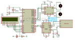
I am doing project on gsm controlled robot using AT89S52 microcontroller in which i'm facing a problem. Microcontroller is not reading the message from the GSM modem (sim900a).
Can anyone please help me regarding this issue.
Here is my code attached below.
Code:
#include<reg51.h>
#include<lcd.h>
#include<uart.h>

#define robot P2

void main()
{
	unsigned char temp,i,j,k,l,m;
	unsigned char read[8],a[8]="forward ",b[8]="backward",c[8]="left    ",d[8]="right   ";
	lcd_init();
	uart_init();
	robot = 0;
	lcd_stringxy(0,0,"GSM Controlled");
	lcd_stringxy(1,0,"Robot");
	
	while(1)
      {
		
	j=0,l=0,m=0;
	while(rx_data()!=0x0d);
		
		while(rx_data()!=0x0a);
			
			if(rx_data()=='+')
			{
				if(rx_data()=='C')
				{
					if(rx_data()=='M')
					{
						if(rx_data()=='T')
						{
							if(rx_data()=='I')
							{
							   while(rx_data()!=',');
								temp=rx_data();
								delay_ms(10);
								tx_string("at");
								tx_data(0x0d);
								tx_data(0x0a);
								tx_string("at+cmgf=1");
								tx_data(0x0d);
								tx_data(0x0a);
								tx_string("at+cmgr=");
								tx_data(temp);
								tx_data(0x0d);
								tx_data(0x0a);

								while(rx_data()!=0x0a);
								while(rx_data()!=0x0a);
								while(rx_data()!=0x0a);
									
								for(i=0;i<8;i++)
								{
									read[i]=rx_data();
								}
								lcd_cmd(0xc0);
								for(i=0;i<8;i++)
								{
									lcd_data(read[i]);
								}
									
								for(i=0;i<8;i++)
								{
									if(read[i]==a[i])
									j++;
									if(read[i]==b[i])
									k++;
									if(read[i]==c[i])
									l++;
									if(read[i]==d[i])
									m++;
								}
									
									if(j==8)
								{
									robot=0x0a;
								}
									if(k==8)
								{
									robot=0x05;
								}
									if(l==8)
								{
									robot=0x02;
								}
									if(m==8)
								{
									robot=0x08;
								}		
									
								}}}}}
		
}	}

- - - Updated - - -

Hi admin,
I'm eagerly waiting for your response please can you tell me what is my mistake.
 
Last edited:

After you get +CMTI: SM,x response you have to send AT+CMGR=x\r command to read the SMS and in that you have to extract the SMS and take the decision. How much is your buffer size because AT+CMGR header itself will be 80 characters.
 

actually i have given the command what you have said me to do.

- - - Updated - - -

Code:
/*--------------------------------------------------------------------------
REG51.H

Header file for generic 80C51 and 80C31 microcontroller.
Copyright (c) 1988-2002 Keil Elektronik GmbH and Keil Software, Inc.
All rights reserved.
--------------------------------------------------------------------------*/

#ifndef __REG51_H__
#define __REG51_H__

/*  BYTE Register  */
sfr P0   = 0x80;
sfr P1   = 0x90;
sfr P2   = 0xA0;
sfr P3   = 0xB0;
sfr PSW  = 0xD0;
sfr ACC  = 0xE0;
sfr B    = 0xF0;
sfr SP   = 0x81;
sfr DPL  = 0x82;
sfr DPH  = 0x83;
sfr PCON = 0x87;
sfr TCON = 0x88;
sfr TMOD = 0x89;
sfr TL0  = 0x8A;
sfr TL1  = 0x8B;
sfr TH0  = 0x8C;
sfr TH1  = 0x8D;
sfr IE   = 0xA8;
sfr IP   = 0xB8;
sfr SCON = 0x98;
sfr SBUF = 0x99;


/*  BIT Register  */
/*  PSW   */
sbit CY   = 0xD7;
sbit AC   = 0xD6;
sbit F0   = 0xD5;
sbit RS1  = 0xD4;
sbit RS0  = 0xD3;
sbit OV   = 0xD2;
sbit P    = 0xD0;

/*  TCON  */
sbit TF1  = 0x8F;
sbit TR1  = 0x8E;
sbit TF0  = 0x8D;
sbit TR0  = 0x8C;
sbit IE1  = 0x8B;
sbit IT1  = 0x8A;
sbit IE0  = 0x89;
sbit IT0  = 0x88;

/*  IE   */
sbit EA   = 0xAF;
sbit ES   = 0xAC;
sbit ET1  = 0xAB;
sbit EX1  = 0xAA;
sbit ET0  = 0xA9;
sbit EX0  = 0xA8;

/*  IP   */ 
sbit PS   = 0xBC;
sbit PT1  = 0xBB;
sbit PX1  = 0xBA;
sbit PT0  = 0xB9;
sbit PX0  = 0xB8;

/*  P3  */
sbit RD   = 0xB7;
sbit WR   = 0xB6;
sbit T1   = 0xB5;
sbit T0   = 0xB4;
sbit INT1 = 0xB3;
sbit INT0 = 0xB2;
sbit TXD  = 0xB1;
sbit RXD  = 0xB0;

/*  SCON  */
sbit SM0  = 0x9F;
sbit SM1  = 0x9E;
sbit SM2  = 0x9D;
sbit REN  = 0x9C;
sbit TB8  = 0x9B;
sbit RB8  = 0x9A;
sbit TI   = 0x99;
sbit RI   = 0x98;

#endif

the below attached code is for lcd
Code:
//NOTES:

//1: This code may be distributed and modified freely .
//2: External Crystal of 11.0592 MHz is assumed.
//3. 16x2 lcd Modules is being operated in Nibble Mode.
//4: Connections to the lcd are assumed as followed:

//		RS		-> P1.0
//		RW		-> P1.1	
//		E		  -> P1.2
//		D4,D5,D6,D7	-> P1.4,P1.5,P1.6,P1.7


#define lcd_DATA P1

sbit lcd_rs = P1^0; 

sbit lcd_rw = P1^1;  			//Must Always be low to allow data to be sent to lcd

sbit lcd_en = P1^2;

void delay_ms(unsigned int n)
{
int i,j;
for(i=0;i<n;i++)
for(j=0;j<124;j++);
}

void lcd_enable()
{
	lcd_en = 1;		//High to low transition
	delay_ms(5);
	lcd_en = 0;		
}

void lcd_cmd(unsigned char cmd)
{
    lcd_rs = 0;			//cmd Mode
    lcd_DATA = ((cmd & 0xF0)|0x04);
    lcd_enable();
    lcd_DATA = (((cmd<<4) & 0xF0)|0x04);
    lcd_enable();
		delay_ms(5);
}

void lcd_data(unsigned char ascii)
{
    lcd_rs = 1;			//Data Mode
    lcd_DATA = ((ascii & 0xF0)|0x05);
    lcd_enable();
    lcd_DATA = (((ascii<<4) & 0xF0)|0x05);
    lcd_enable();
		delay_ms(5);
}

void lcd_init()
{
	
	lcd_cmd(0x02);		//Enable 4 bit mode
	  
	lcd_cmd(0x28);		//Set interface 4 bit 2 line

	lcd_cmd(0x08);		//Enable display/cursor
	
	lcd_cmd(0x06);		//Set cursor move, Move cursor right
	
	lcd_cmd(0X0C);		//Turn on display
	
}

void lcd_gotoxy(unsigned char row,unsigned char column)			//move cursor to the specified position
{
   if(row==0)
    {
	 lcd_cmd(0x80+column);
	}
   else if(row==1)
	{
	 lcd_cmd(0xC0+column);	
	}	
}
void lcd_number(int val,unsigned int field_length)			// Function to display number 
{
	char str[5]={0,0,0,0,0};
	int i=4,j=0;
	while(val)
	{
	str[i]=val%10;
	val=val/10;
	i--;
	}
	if(field_length==-1)
		while(str[j]==0) j++;
	else
		j=5-field_length;

	if(val<0) lcd_data('-');
	for(i=j;i<5;i++)
	{
	lcd_data(48+str[i]);
	}
}

void lcd_string(unsigned char *str)
{
	
		
		while(*str!='\0')	//Till null character is encountered
		{
			lcd_data(*str);
			str++;
		}
}

void lcd_stringxy(unsigned char row, unsigned char col, unsigned char *lcd_string)
{
	lcd_gotoxy(row,col);
	while (*lcd_string) 
	{
		lcd_data(*lcd_string++);
	}
}
void lcd_numberxy(unsigned char row, unsigned char col,int val,unsigned int field_length)
{
	char str[5]={0,0,0,0,0};
	int i=4,j=0;

	lcd_gotoxy(row,col);

	while(val)
	{
	str[i]=val%10;
	val=val/10;
	i--;
	}
	if(field_length==-1)
		while(str[j]==0) j++;
	else
		j=5-field_length;

	if(val<0) lcd_data('-');
	for(i=j;i<5;i++)
	{
	lcd_data(48+str[i]);
	}
}


and this is for UART
Code:
void uart_init(void)	   // INITIALIZE SERIAL PORT
{
	TMOD = 0x20;	  // Timer 1 IN MODE 2-AUTO RELOAD TO GENERATE BAUD RATE
	TH1 = 0xFD;	// LOAD BAUDRATE TO TIMER REGISTER
	SCON = 0x50;	  // SERIAL MODE 1, 8-DATA BIT 1-START BIT, 1-STOP BIT, REN ENABLED
	TR1 = 1;			      // START TIMER
}
void tx_data(unsigned char serialdata)
{
	SBUF = serialdata;			// LOAD DATA TO SERIAL BUFFER REGISTER
	while(TI == 0);				// WAIT UNTIL TRANSMISSION TO COMPLETE
	TI = 0;		// CLEAR TRANSMISSION INTERRUPT FLAG
}
unsigned rx_data(void)	
{
	while(RI == 0);				// WAIT UNTIL DATA IS RECEIVED 
	RI = 0;					// CLEAR FLAG
	return SBUF;				// RETURN SERIAL DATA
		
}
void tx_string(unsigned char *str)
{
	while(*str)
	{
		tx_data(*str);
		str++;
	}
	
}
// END OF PROGRAM

- - - Updated - - -

can you please check all of my codes attached and give me a solution.
 

What is this ?

Code:
while(rx_data()!=',');
temp=rx_data();

What if SMS index is greater than 9 ?

Are you sure SMS index is not greater than 9 ?

Are you using SIM memory for SMS ? If not set to SIM memory then set it to SIM memory using AT+CMPS command. Look SIM900 manual for AT+CMPS command.
 

yes i'm sure SMS index is not greater than 9. No i'm not using sim memory. But i want that to be in my microcontroller(AT89S52). Actually my project aim is that as i send message to gsm modem to move in the direction i give it must be displayed in the lcd display and the output is the driving of robot. So can you please give me code to do that action.

my code is working till it displaying GSM CONTROLLED ROBOT after that if i send message to GSM modem my microcontroller is not responding for that message. So please help my regarding this project and give me the code.

This is my circuit in which i am using AT89S52 microcontroller.

GSM-Controlled-Robot-Circuit-Diagram.jpg
 

Zip and post your complete project. Are you using Keil uVision ? If yes, which version ? I can only give code which uses Serial Interrupt. You are not using Serial Interrupt in your code.

You need to use AT+CPMS command once during GSM Initialization. It will set to use SIM memory and when you send SMS to modem it will be stored in SIM and when you issue AT+CMGR=x\r command it will read from SIM memory. When GSM is connected to 8051 it will not be using phone memory for SMS because there is no phone memory available. You please use the AT+CPMS command. I hope it will work. if you still don't get it working then I will provide my C Code.
 

Already i have posted my entire code. i am using keil uvision2 version
 

i have checked my gsm modem giving commands from hyperterminal it is working, but when i use a microcontroller it is not reading the message what i send from other mobile.
 

I have checked it baudrate is also matching
 

Hi,
As you said me to attach the zip file. Now i attached my entire project hope these are enough and please help me regarding this issue.


Thanks & Regards,
Cnutou.
 

Attachments

  • GSM-controlled-robot.rar
    68.2 KB · Views: 80
  • GSM-Controlled-Robot-Circuit-Diagram.jpg
    GSM-Controlled-Robot-Circuit-Diagram.jpg
    226.1 KB · Views: 90

i have checked my gsm modem giving commands from hyperterminal it is working, but when i use a microcontroller it is not reading the message what i send from other mobile.

Can you connect the MCU to the serial terminal? If so you will make your life easier by seeing what exactly you are sending from the MCU to the GSM and realize if this matches to the string you are sending from the serial terminal to the GSM. Just make sure that serial terminal uses the exact same communication settings (ie baudrate) in both cases.
 

Status
Not open for further replies.

Part and Inventory Search

Welcome to EDABoard.com

Sponsor

Back
Top