Continue to Site
Follow along with the video below to see how to install our site as a web app on your home screen.
Note: This feature may not be available in some browsers.
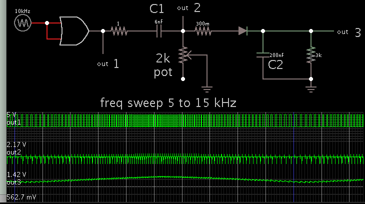
Most straightforward way is to trigger a monostable multivibrator and then integrate the output with an RC filter.whats the best option I have to convert frequencies between 5Khz - 15Khz into analog voltage signal varying between 1-3.3v ?
its a square with 50% duty cycle 0-3.3v peak-to-peak.If it is not a sinewave input, then a one-shot and charge bucket can do the job.
lowest effort with most precisionHi,
What do you mean with "best"?
Best precision, lowest part count, lowest cost, lowest effort or something else?
its a square wave with 50% duty cycle, 3.4 v peak to peak.Specify: Voltage levels and signal waveform.
I am aware of this method but I cant use my micro as I am using all of its timers for other purposes.You could use an 8 pin microcontroller. Use a timer to measure the frequency (should be able with error below 0.1%. Depends on frequency range)
And generate a PWM. Control an analog switch connected to 3V3 and 0V...then add a low pass filter.
You ask about frequency --> voltage conversion.I like these V-to-F chips , can I use these ?
Most straightforward way is to trigger a monostable multivibrator and then integrate the output with an RC filter.
Here is a simple circuit using a 555 timer chip:
https://www.elprocus.com/frequency-to-voltage-converter-using-555-ic/
These are typical questions to be answered by the datasheet.hi Klaus i am not that rich yet to afford custom made chips , isnt there a frequency to voltage chip that covers some general input frequency range ?
I talked to digikey people just now and they are saying i cant use FTV chips for my application since i have a digital input square wave .. is that true ?
As said before: use a low pass filter.2- how can i convert the PWM voltage output to pure DC ?
It will not be linear to f, but it will be about linear to 1/f.It should be very accurate and linear.
Here is a simple circuit using a 555 timer chip:
https://www.elprocus.com/frequency-to-voltage-converter-using-555-ic/
An XR4151 can do Both ways:
Frequency to Volts or Volts to Frequency.