Continue to Site

Welcome to EDAboard.com

Welcome to our site! EDAboard.com is an international Electronics Discussion Forum focused on EDA software, circuits, schematics, books, theory, papers, asic, pld, 8051, DSP, Network, RF, Analog Design, PCB, Service Manuals... and a whole lot more! To participate you need to register. Registration is free. Click here to register now.

[SOLVED] Servo motor Driver and Pic32 microcontroller Problem?

Status
Not open for further replies.

nick703

Advanced Member level 1
Joined
Oct 17, 2011
Messages
422
Helped
21
Reputation
44
Reaction score
22
Trophy points
1,298
Location
surat
Activity points
3,987
Hello All

First of all I have pic32Mx575F256H and Panasonic Minas-A4E series Servo motor Driver. Below is the Driver Image.
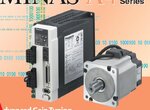
Minas-A4E.JPG

Now below is the Diagram of servo motor Driver.
Wiring Connection.JPG

Now Problem Is When I connect My Pic32 Microcontroller Pulse and Dir Signal Connected this Servo driver that time Servo is not working. is that any problem regarding pulse and direction signal . i connect Directly this signal to Servo motor Driver. And pic32 has a Open drain i/p o/p so is that required Any Pull up Resister to Signal working Proper Connection?

Do i need any other Ic for this purpose ?
 

If the PIC32 pin is Open-Drain then you will need a pull-up resistor. A 4.7k will be fine. Pull-up to +3.3V.
 

ok then should i have connected directly (Pull up) signal to Servo motor Driver ?
 

I have not used big servos. I have only used mini servos which rotate 180 degrees. They need 3 different pulses with different pulse width to rotate -90, 90 and 180 degrees.

I don't know your about your Servo. Post the datasheet of your Servo. You have to pull up the PIC32's Open-Drain pin to +3.3V and connect the Open-Drain pin to the pulse input of Motor Driver. Maybe your motor needs additional signals. That can be answered only after checking the motor datasheet.
 

How many wires the motor is having? Are they connected correctly? Please try to reverse a pair (one at a time) and see the result. Can the controller supply enough current for the motor (or, do you need another driver)? What are the inputs to the controller?
 

This is a three phase motor with encoder and brake function. How you are connecting the PIC output to the motor driver? Initially you may not bother about the encoder and the brake function.
 

In My First post i have figure out the connection of my Pic micro controller. I have connected My Pic microcontroller Pulse and Direction pin to Servo motor Driver Pulse2 and sign2. Below is the Wiring Connection.

PULS1 --> DC 24v Supply
PULS2 --> PIC micro controller Open Drain Output (Pulse)
SIGN1 --> DC 24v Supply
SIGN2 --> PIC micro controller Open Drain Output (Direction)

Now I have stepper motor Driver and when i connected this Pulse and Direction Signal of Micro controller that time stepper motor working but not working with servo motor driver and servo motor.
 

For the pins used for PULS2 and SIGN2 add a 4.7k pullup resistor (pulled high to +3.3V).

For the Servo Driver's pins which needs pulse of 24V use a transistor/mosfet between PIC32 and Servo Driver's pins (pins which need 24V pulse). Remember Transistor/mosfer (single) will invert the signal. So, in code invert the data written to the corresponding signal pin.
 
Sorry but i got the First line as you said i add pullup resistor and pulled high to 3.3V

but in second Statement of Your You said 24V Pulse using any transistor or Mosfet but in Servo motor Driver PULS1 AND SIGN1 is directly connected to the 24V Supply. So confusing me regarding this term can you please advise me a circuit in which pin i have to add transistor .

Is Transistor is placing on PULS1 OR PULS2 side.
 

I told you earlier I have not used big Servos or Servo Drivers. I thought those 24V pins need a pulse. if they just need 24V power then jsut connect them to 24V power supply. No need for transistor to drive them or no need for any pulse for those pins.
 

Now I have stepper motor Driver and when i connected this Pulse and Direction Signal of Micro controller that time stepper motor working but not working with servo motor driver and servo motor.

Servo motor needs different connections. How you have connected the servo motor? Servo motor needs three phase power.
 

He is not asking the connection between Servo Drivers output and motor. He is asking connections between PIC32 and Servo Drivers Control inputs.
 

PULS1 --> DC 24v Supply
PULS2 --> PIC micro controller Open Drain Output (Pulse)
SIGN1 --> DC 24v Supply
SIGN2 --> PIC micro controller Open Drain Output (Direction)
The connection has most likely already burned the PIC32 outputs and might also have damaged the controller inputs, or did you luckily omit the ground connection between 24V supply and PIC 32 circuit?

Unfortunately there's no current threshold specification in the manual. I presume, simply connecting PULS1/SIGN1 to the PIC32 3.3V supply should be O.K. with the internal 220 ohm series resistors. Or use an output driver and 12 or 24V logic, with the respective current limiting resistors mentioned in the "Position Control" wiring example.
 
Ok Now i have tried all type of configuration of servo motor rotate using Micro controller but every time i failed.

Now i have purchased 5 axis motion control card and connect pulse and dir to direct servo motor Driver and working perfact.

Then what is the Difference to using micro controller pulse i have simply Pulse off on pattern in coding with 50uF delay. and also i have using 26ls31 IC for Pulse + and Pulse - Signal . but not working please advise me .
 

I do not think PULS1 and SIGN1 are to be connected to DC 24V supply. These are floating logic level connections. You need to connect them to GND. Are you using command pulse A or command pulse B? Connect SIGN2 also to ground and send some pulses to PULS2.
 

Tried Still not working.

I have some another Servo motor Driver Fuji. Below is the Datasheet

View attachment fuji servo manule.pdf
Now See Page no. 57

I Don't know which type of Pulse Use. Datasheet Says Open Collector Output pulse of Microcontroller use.

Below is the simple code
Code:
	mStepper_B_For();			         //Dir Pin = FORWARD;					
	mStepper_B_Off();			         //pluse pin = OFF
         	Delay_us(25);
	mStepper_B_On();                                ////pluse pin = ON

This code in loop for evrey 30mSec to 1000mSec.

I get Value on multimeter for this 2 pin. and this is a open Drain output right.

Now i use this pin Output to 3.3 V pullup using 1k ohm resistor and this output signal goes to PC817 opto coupler is. and output Signal is pull up to 5V using 750ohm registor. and this output signal is going to HCF40106 IC hex inverter. and that ic output signal goes to AM26C31 ic and i get 2 output of Pulse + and Pulse -.

And this output i connected Fuji Servo motor Driver Page no. 57 (2)No. Open Colletor (24V).

Now Every thing tried but not getting to rotate servo motor Drive Run.

please Suggest any Solution.
 

Status
Not open for further replies.

Part and Inventory Search

Welcome to EDABoard.com

Sponsor

Back
Top