Continue to Site

Welcome to EDAboard.com

Welcome to our site! EDAboard.com is an international Electronics Discussion Forum focused on EDA software, circuits, schematics, books, theory, papers, asic, pld, 8051, DSP, Network, RF, Analog Design, PCB, Service Manuals... and a whole lot more! To participate you need to register. Registration is free. Click here to register now.

2.5 kW Full bridge boost converter

Status
Not open for further replies.

Error_Amplifier

Junior Member level 1
Joined
Jan 20, 2016
Messages
17
Helped
0
Reputation
0
Reaction score
0
Trophy points
1
Activity points
134
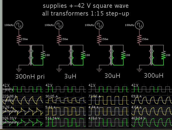
42 volt input from a battery source and 500 volt DC output is required. The switching frequency is 100 kHz. Full bridge with mosfets on the primary side and full bridge diode rectifier on the secondary side.

Please provide help for the transformer design and the feedback control implementation.
 

Please provide help for the transformer design

Your post mentions more than one topology. It is not clear which one you wish to use.

Anyway since you mention a transformer, I adapted your specs to a previous experimental simulation. Each transformer has a different primary Henry value (in steps of 10X).


The V and A waveforms tell the story. It looks as though the first and last examples are not very efficient.
 
woops, just seen your title says 2500W. OK, I reckon you would be better off using a simple boost converter to boost from 42V to 200V, say, then do an LLC to go from 200V to 500V...otherwise there is loads of current in your primary and its difficult to wind,,unless you have foil winding.....I reckon i'd do 200-500vdc as said, and do an LLC with split section bobbin, as its easier to get lower conduction losses with a split section bobbin setup when using round section ECW.
Otherwise, you are going to need foil winding if you do 42v to 500vdc in a full bridge stage alone.
And you can make the 42v to 500vdc boost in three interleaved stages if you want to make it easier....otherwise as you know, your input current is over 50 Amps average......50^2*0.001 = 2.5W, so every milliohm of trace inductance, dissipates 2.5W with 50A average current.

- - - Updated - - -

LLC is master at high power and high vout, because the vout ringing on the output diodes is nothing.

Control the LLC with an error amplifier as per usual way.....Infineon do a good llc control chip....IS2H..or something...or use a microcontroller and then you can do adaptive dead time control for lighter loads.
 
2500 watts at 70% efficiency = 85 amps. At 100 KHZ the wire becomes extra difficult.

Treez idea of 3 interleaved boost converters is a good idea. I assume he means a real boost converter using a switch and an inductor not a transformer and a bridge. If true isolation is required from the battery pack then a full bridge could be used to go from 500 vdc to 500 vdc keeping the current down and the transformer easier to design. Now at 70% efficiency and 500 volt primary you would only need a 7.2 amp primary.
 
Good point Flapjack I forgot to ask about isolation.
Indeed , if no isolation is required, and your size limits are large, then just do a very low frequency hulking great big boost converter with some iron powder type inductor, and some humongous igbts, and just do it like that...42vdc to 500vdc, with a simple huge, low frequency boost converter
 
For isolation, 3 x 850 watt transformers are a good place to start, say ETD49 each, 100kHz is a little ambitious for 500V out, but SiC diodes could do it, 1.7 amps from each transformer...

The i/p current to each Tx is 20A, which is manageable, one set of fets (4) could quite possibly drive the 3 Tx's

if Tx's made the same they will balance fairly well, you will need to go phase shift PWM at 100kHz, unless you have plenty of room for heat-sinking of the fets (and snubbers)

Good Luck..!
 
Full bridge.JPG

I want to use full bridge as a step up converter from 46 volts to 500 volts. The design to be implemented has been shown in the attached image.

The problem with this design is with the transformer. The leakage inductance causes a drop in the output voltage. How should I design the transformer, so as to ensure that leakage inductance is negligible.
 

Wind three identical transformers, each with a ratio of around 4:1 (42v to 168v) at about 850 watts each.
Provide each transformer with its own bridge rectifier, filter choke and filter capacitor.

Connect the transformer primaries in parallel.
Connect all the dc outputs in series, 3 x 168v = 504v.

There will be far fewer problems designing a transformers that has a ratio of only 4:1, less secondary turns means a higher self resonant frequency.
And much easier finding suitable rectifier diodes at the lower voltage.
 
I have seen Ultra fast diodes which can operate at 1 kV. So I'm not considering the interleaving of secondary side transformer now.

Please tell me, how can I ensure that my transformer is made such that the leakage inductance is less than 10 nH?

The leakage inductance leads to decrease in the primary side voltage across the transformer.

Please guide me.
 

Error_Amplifier, I do not know why you think leakage inductance leads to lower primary voltage. But leakage inductance does cause you to add higher power snubber's because of voltage spikes.

Also i think what Warpspeed is saying in post #9 is with lower self resonant frequency the time constant of the transformer may be to slow. Let's see if he confirms this.

Edit
I was trying to say have trouble oscillating and or starting.
 
Last edited:
Its going to be rather difficult to wind a single 500 volt secondary that will end up with a self resonant frequency high enough to work at anything like 100 Khz.
Try it and see...
 
Please tell me, how can I ensure that my transformer is made such that the leakage inductance is less than 10 nH?
Not possible, by an order of magnitude or so. But you shouldn't need such low leakage. So long as the turns ratio is sufficient, the secondary voltage should be taken care of by the feedback loop.
 
Please tell me, how can I ensure that my transformer is made such that the leakage inductance is less than 10 nH?
you can't, as per post #9 3 x Tx's with each o/p rectified and then series'd will do the job far more effectively, with lower overall losses...
This is not a job for a newbie really, remember 500VDC can be lethal, so be careful...!
 
How is Watt per kg calculated for a core material ?

say for N87 the W/kg is :
8.08*10^-7*f^(2.065)*Bac^(3.059)

Please tell me how do I calculate the W/kg for N95 material at 2500 permeability, at 100 deg. Celsius.
 

Wind three identical transformers, each with its own bridge rectifier, filter choke and filter capacitor.

Connect the transformer primaries in parallel.
Connect all the dc outputs in series

Please can u share the diagram.
 

thanks everyone for the suggestions.
are there any pwm control ic's with integrated driver ckt for 65 volt input and 450 volt with 5.5 amps (2.5kw) output having output voltage control and protection ckt.
 

Please suggest me winding techniques on ETD core bobbin (coil former).

I tried to wind secondary-primary-secondary interleaved windings, in order to reduce the leakage inductance using an AWG wire.

I wanted to know that by using a foil will the leakage reduce further ?
Please suggest winding techniques.
 

Status
Not open for further replies.

Part and Inventory Search

Welcome to EDABoard.com

Sponsor

Back
Top