Continue to Site

Welcome to EDAboard.com

Welcome to our site! EDAboard.com is an international Electronics Discussion Forum focused on EDA software, circuits, schematics, books, theory, papers, asic, pld, 8051, DSP, Network, RF, Analog Design, PCB, Service Manuals... and a whole lot more! To participate you need to register. Registration is free. Click here to register now.

low pass filter analysis

Status
Not open for further replies.

m_kuty

Member level 2
Joined
Mar 2, 2015
Messages
46
Helped
1
Reputation
2
Reaction score
1
Trophy points
8
Activity points
333
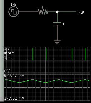
I have a circuit of low pass filter. the input is 0 to 2.5 Volt. i need the output is 1 volt as DC signal. and I need the values of the R1, R2, R3 and C1. How much should be?

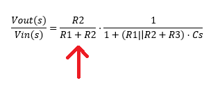
the circuit analysis please.

https://obrazki.elektroda.pl/3183955600_1454171405.jpg

M_kuty
pass_fliter.jpg
 

R3-C1 create a triangle wave riding a DC component. For the RC time constant, it should be much longer than the period of incoming pulses.

R1-R2 form a voltage divider. I think you only need slight voltage reduction, if any. Therefore I think R1 should be small, R2 should be large.

- - - Updated - - -

Think of R1-R2 as a potentiometer. Dial it until you get 1V output.
 

Average value of the input voltage is 0.25*2.5V = 0.625 V, respectively you can't get more than this DC level without an amplifier. 1 V can't be achieved.

To be able to calculate a low pass time constant, it's necessary to specify input frequency and acceptable residual output ripple.
 

thank you BradtheRad and FvM.
if I change the duty cycle to 75%. what will be the average value of the input?
how can the input frequency calculate ?
 

Average value of the input voltage is 0.25*2.5V = 0.625 V, respectively you can't get more than this DC level without an amplifier. 1 V can't be achieved.

To be able to calculate a low pass time constant, it's necessary to specify input frequency and acceptable residual output ripple.

2 questions:

1)DC voltage is average voltage not RMS value? The RMS value of an AC supply is the steady DC which would convert electrical energy into thermal energy at the same rate in a resistance. So if we had at the output a resistance, why use average instead of RMS value? DC = average? RMS acts like beeing DC voltage too...

2)"About the ripple": Is not the output a square wave too? If there is any ripple, give me R and C values for a simple RC low pass filter to simulate it (not because I do not believe you, because I can not find R and C values to see that ripple at the output).


if I change the duty cycle to 75%. what will be the average value of the input?
average input voltage=0.75*2.5 V

how can the input frequency calculate ?
Your signal generator I guess..
 
Last edited:

The steps are:

at the junction of R1:R2:R3, you see a voltage source with series resistance R1 and parallel resistance R2.

The voltage at this junction will be Vin*R1/(R1+R2). This is input to the R3:C1 low pass filter with time constant R3*C1.

Actually you need to add to R3 the resistance of the source (R1 in series and R2 in parallel).

Your low pass filter output will be always less than 2.5V*0.25 duty cycle.

You choose C1 depending on the desired 3db cut-off point.

- - - Updated - - -

2)"About the ripple": Is not the output a square wave too? If there is any ripple, give me R and C values for a simple RC low pass filter to simulate it (not because I do not believe you, because I can not find R and C values to see that ripple at the output).

In absence of C1, the output will be a square wave with the amplitude and source impedance changed. When you insert C1, it will integrate the voltage and the output will look more like triangular wave (depends on the value of C1 and the input frequency). With very large value of C1 and with a high enough frequency, you will get a stable DC value.
 
  • Like
Reactions: CataM

    CataM

    Points: 2
    Helpful Answer Positive Rating
I hope this simulation is not cheating (in regard to the exercise questions, that is).

It answers several questions in this thread. It demonstrates behavior of RC time constant=1, with a frequency of 1 Hz.

1 Hz square wave
1 F
1 ohm

4795460000_1454215760.png


By some mathematical quirk, the capacitor points out the definition of the RC time constant. It reaches 63% of applied voltage after one time constant.
 
  • Like
Reactions: CataM

    CataM

    Points: 2
    Helpful Answer Positive Rating
The full transfer function of the filter showed by the OP in post #1 is this one:


Regarding the term pointed with the arrow, to make it value "1" so then acts like the simple RC low pass filter, it is needed high R2 and low R1 which then changes the time constant etc..

My question is: Is not better to use the simple RC low pass filter rather than the other one?
 

Status
Not open for further replies.

Similar threads

Part and Inventory Search

Welcome to EDABoard.com

Sponsor

Back
Top