Continue to Site

Welcome to EDAboard.com

Welcome to our site! EDAboard.com is an international Electronics Discussion Forum focused on EDA software, circuits, schematics, books, theory, papers, asic, pld, 8051, DSP, Network, RF, Analog Design, PCB, Service Manuals... and a whole lot more! To participate you need to register. Registration is free. Click here to register now.

op amp/FET ramp generating coil driver stability problem

Status
Not open for further replies.

mrln55

Junior Member level 2
Joined
Jun 11, 2013
Messages
21
Helped
4
Reputation
8
Reaction score
4
Trophy points
3
Activity points
230
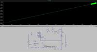
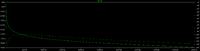
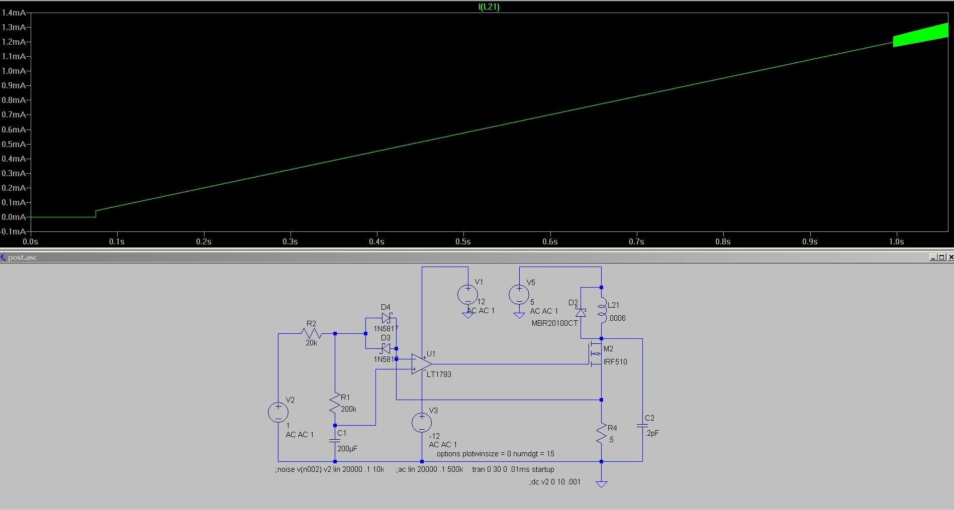
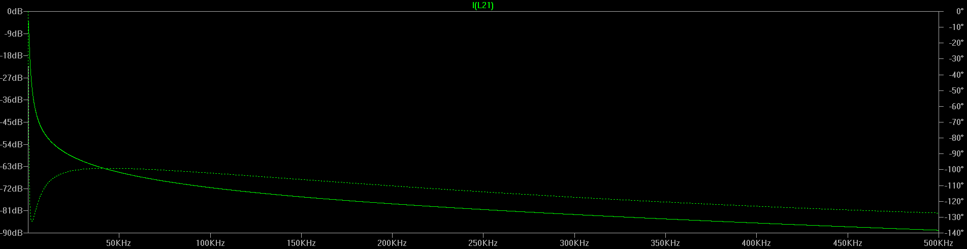
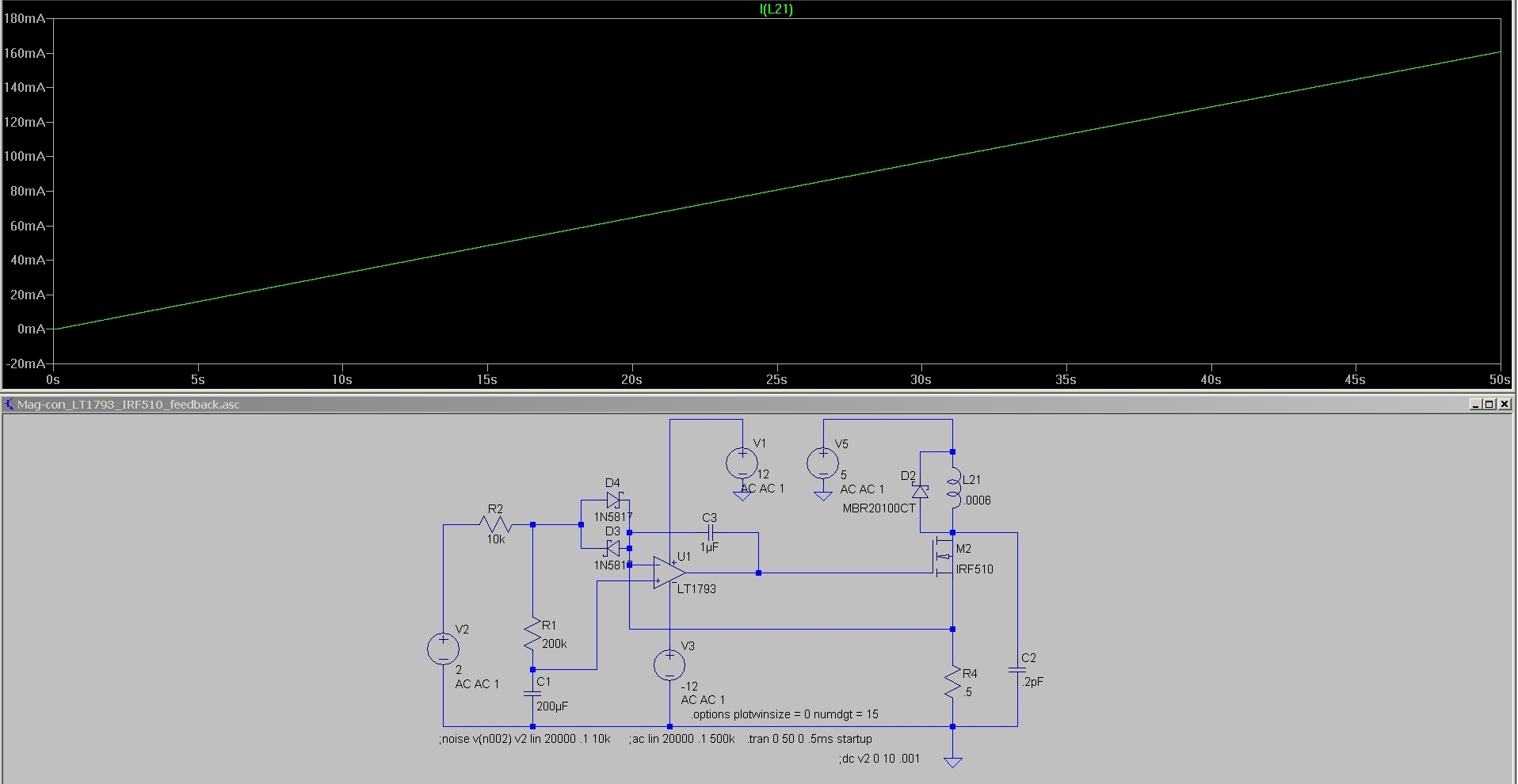
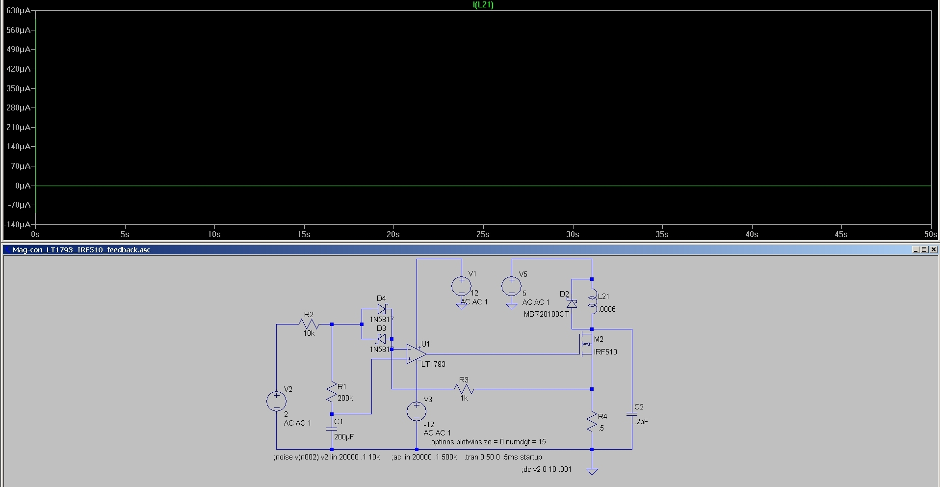
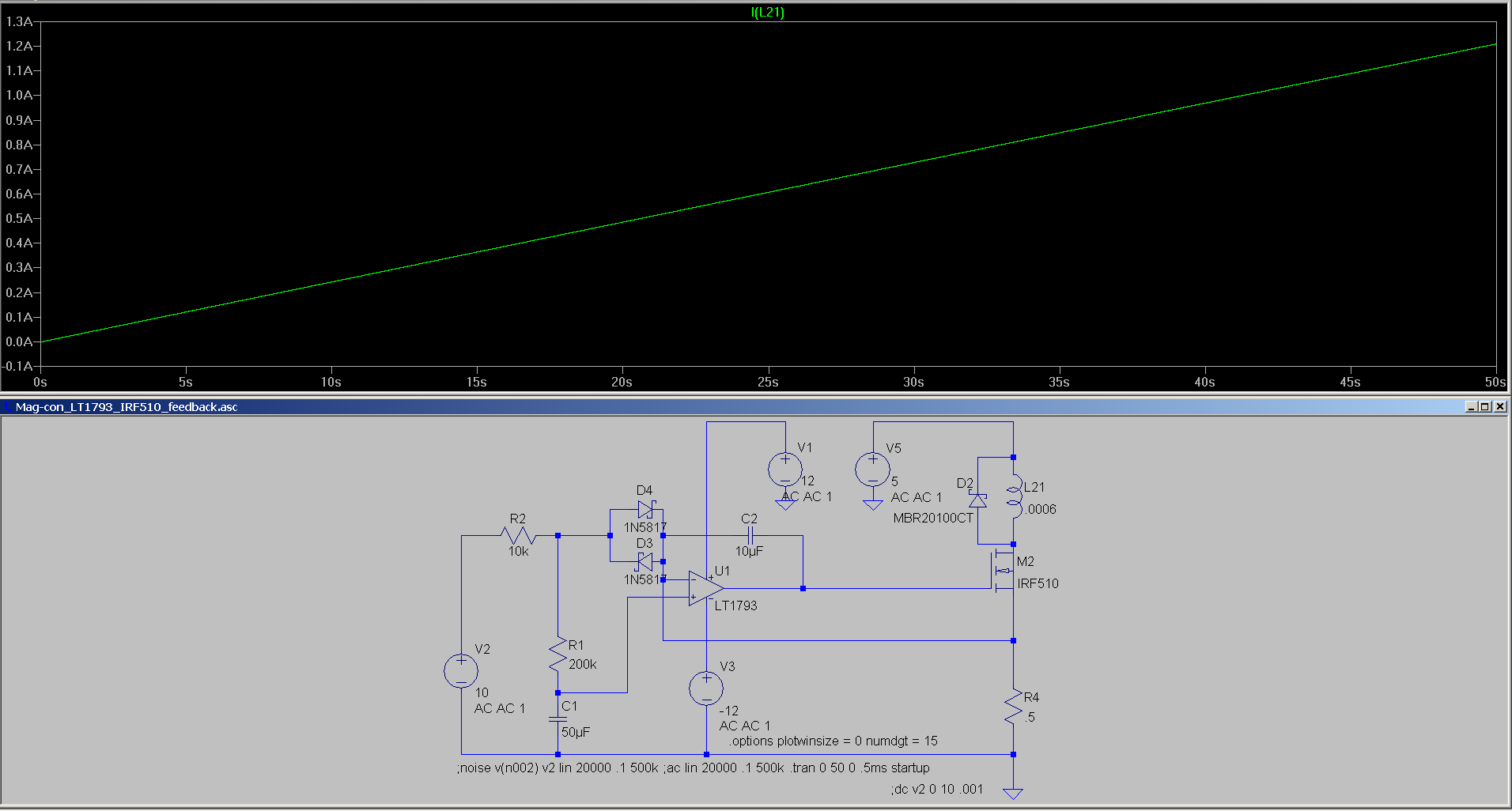
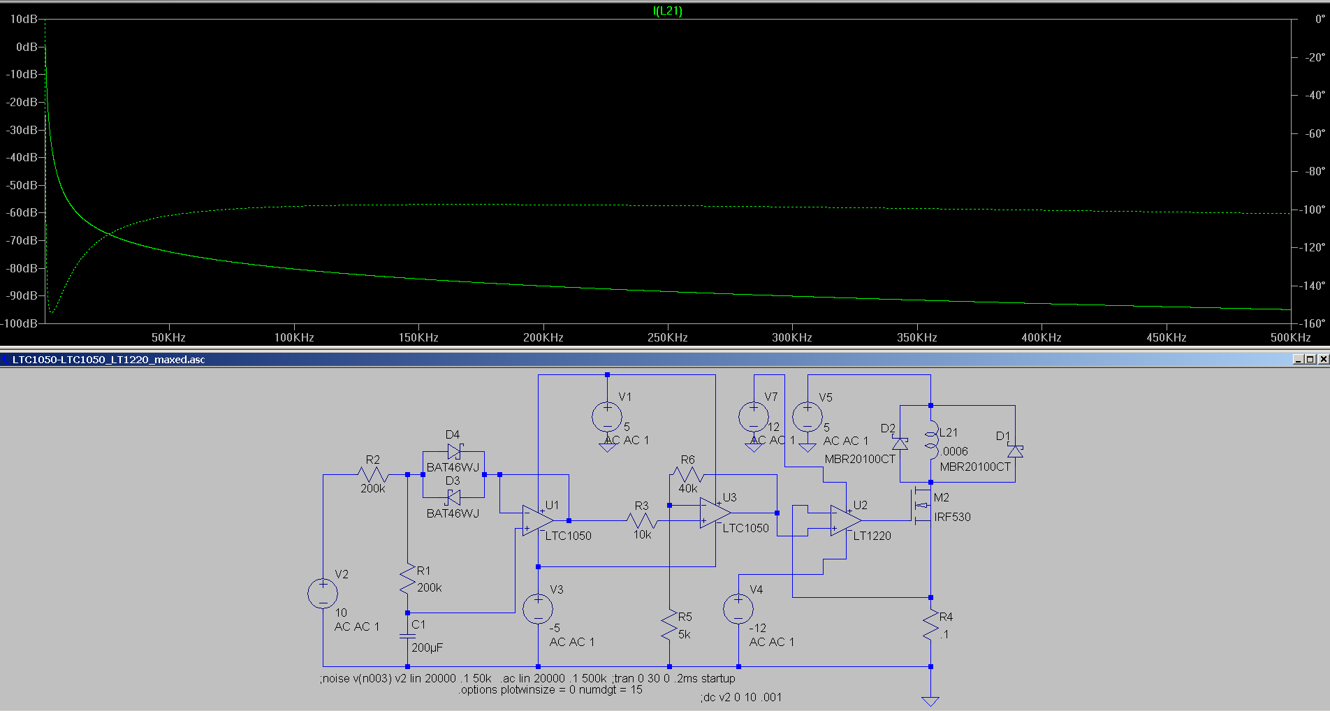
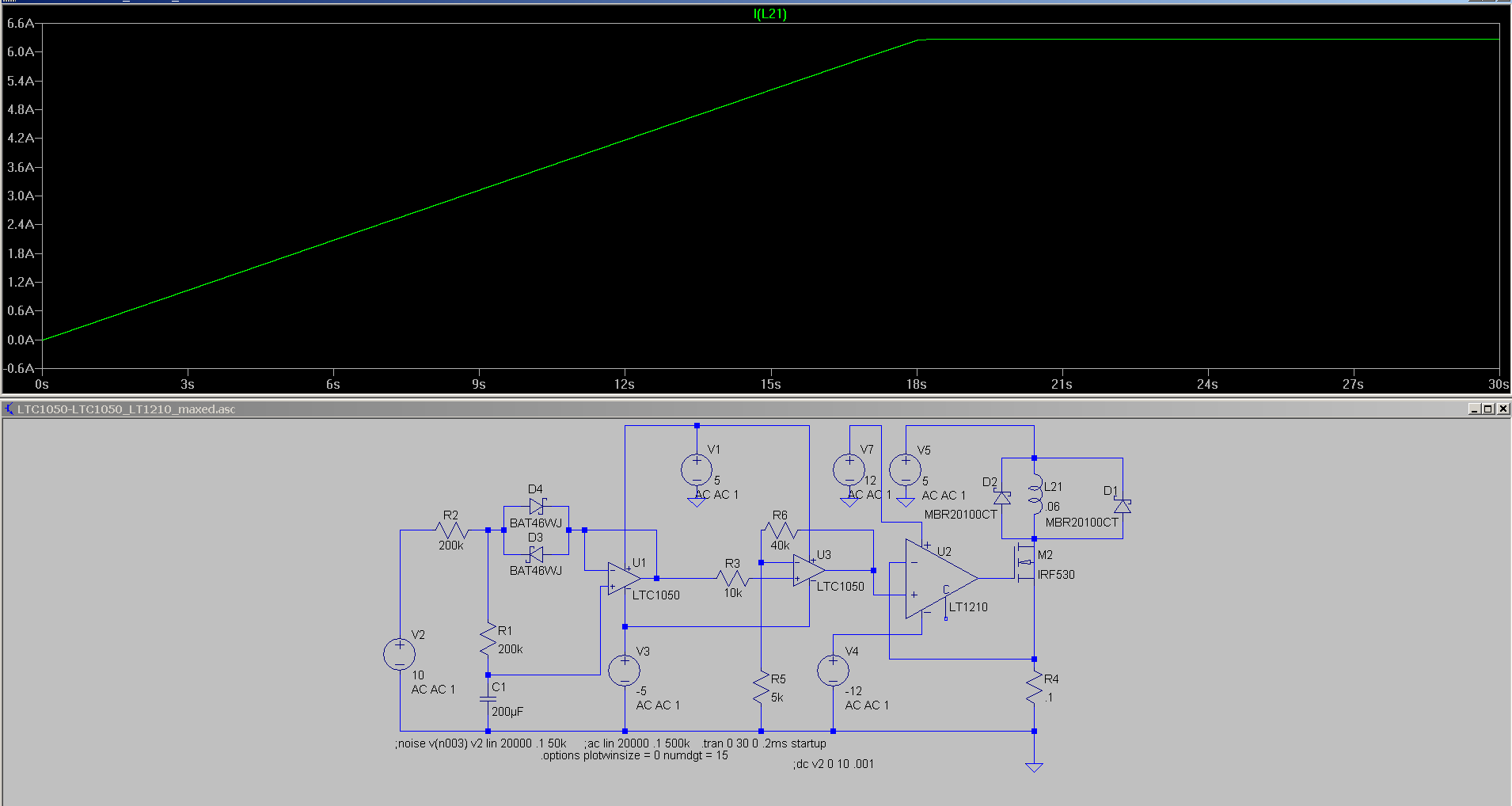
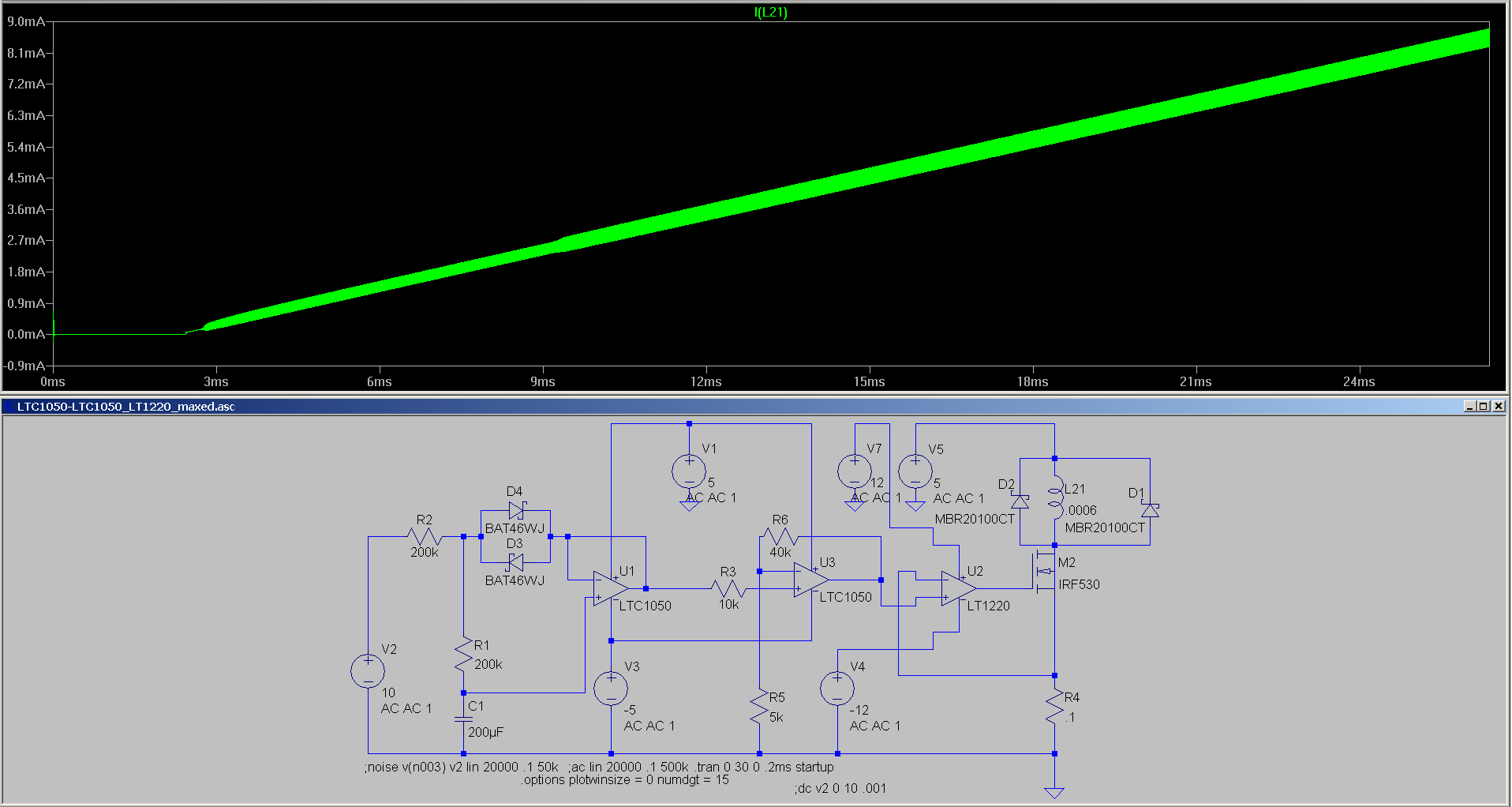
I have simulated an LT1793 op amp/IRF510 FET ramp generator with an inductive load and the simulation oscillates, but the phase magnitude plot doesn't seem to indicate a stability problem (see attached images). If C2 is increased to 1uF, the oscillation is suppressed in the simulation, but I would rather not have C2 in the circuit, since it allows some of the coil current to bypass R4. The circuit is intended to provide a 30 second ramp to a current of 20mA to 1.5 amps using various combinations of V2, R1, R2, and C1. Is there a compensation network that would improve the stability of this circuit or is there a better alternative for driving a coil?


the phase magnitude plot doesn't seem to indicate a stability problem (see attached images).
To say so with some reason, you would have performed the AC analysis with a parametric sweep of output current set point. Did you?

The problem is that transistor gm varies with drain current, loop gain does respectively. In addition, large signal effects (e.g. OP slew rate) can cause instabilities that aren't visible in the loop gain characteristic. MOSFET current sources typically require an additional AC feedback from OP output to input for unconditional stability.

I don't see a reasoning for the input clamp diodes in LT1793 data.
 

Thanks for the response. The clamp diodes provide constant-current charging/discharging of C1 through R1 so that a linear ramp is obtained instead of a sawtooth. I am using LTSpice for simulation and I am not aware of a capability for doing a parametric sweep in conjunction with the AC analysis, although I have used the DC sweep capability.
 

Hi,

I agreee.

The feedback line from R4 back to U1_In- needs a series resistor.
The value is not critical. Try 1k.

Add a capacitive feedback from U1_out to U1_In-.
Try 1nF.

If the oscillation still exists, then try to increase R.

Klaus

Thanks for the suggestions. The 1k resistor probably introduced too much of a voltage drop, but I found that a .5uF (or larger) feedback capacitor suppressed the oscillation


Hi,

I agreee.

The feedback line from R4 back to U1_In- needs a series resistor.
The value is not critical. Try 1k.

Add a capacitive feedback from U1_out to U1_In-.
Try 1nF.

If the oscillation still exists, then try to increase R.

Klaus

- - - Updated - - -

Hi,

The 1k resistor probably introduced too much of a voltage drop
I doubt that.
The 10pA of input bias current multiplied with the 1k givens 10 nV. Is 10nV too much voltage drop?
***
You either use resistor OR capacitor. It is not an alternative solution. You need both in one circuit.

Klaus
 
  • Like
Reactions: mrln55

    mrln55

    Points: 2
    Helpful Answer Positive Rating
That FET load is hugely capacitive and most op amps aren't real
happy about that kind of loading. Often see a series resistor at
the op amp output, feedback inside, load outside when the load
is just a dumb shunt C - but you want feedback from the source
sense resistor, so this is not really an option. Your compensation
network needs to tolerate the not only capacitive, but "busy"
(when you hit Miller plateau, which is exactly where this setup
will operate) output loading. Maybe you want a high power op
amp with more grunt to give, because too much C load can put
you onto internal current limit and break the loop temporarily
(or "motorboat" in and out of current limit as you slew).
 

That FET load is hugely capacitive and most op amps aren't real
happy about that kind of loading...

Hi Dick,

As an alternative, I have looked at an LT1210 high current op amp and it is more stable than the LT1793, however, it has a power dissipation of about 800mW and due to its package, it is awkward to assemble it in a circuit and get a good thermal ground. The LT1210 works well by itself for lower currents, but at higher currents a driver/FET is required. I have tried using a buffer amp or using a FET with a much smaller gate charge, but the oscillation still crops up. I think that the root of the problem is the interaction between the FET and the .6mH coil. I should add that before I added the diodes to improve the ramp linearity, I used only an RC network at the input and the oscillation would sometimes occur in the simulation. I am not that well-versed in dealing with poles and zeroes, so I have been relying on the phase magnitude plots in LTSpice and selecting components for which I can get a negative gain at -180° phase shift for the current in coil.

mrln55

Note to Klaus, FvM, and Dick:

Since I first posted this thread I have been repeatedly getting a message that I am banned from the forum after logging in (see attached). I have been logging out, deleting cookies and logging in each time with some success. I don't know why I would be banned, but If I don't reply to an open issue, it may be the result of the "ban."

thanks for your help,

mrln55
 

Attachments

  • ban.png
    ban.png
    53.5 KB · Views: 61

Nothing has been yet said about dynamic requirements. It's almost easy to make a stable MOSFET current source with a general purpose OP as long as it must no be particularly fast. Previously discussed AC bypass together with a small series resistor isolating the gate capacitance is sufficient. If your application is in the moderate speed rate (e.g. rise time > 100 µs), you don't need to search for exotic OPs and similar stuff.

I'm helpless about the "banned" error message. Apparently some kind of forum software bug. Never saw it before.
 

Hi,


- - - Updated - - -

Hi,


I doubt that.
The 10pA of input bias current multiplied with the 1k givens 10 nV. Is 10nV too much voltage drop?
***
You either use resistor OR capacitor. It is not an alternative solution. You need both in one circuit.

Klaus


Hi Klaus,

The simulation shows the current in the 1k resistor to be about 2mA (see attached).

mrln55
 

Hi,

The simulation shows the current in the 1k resistor to be about 2mA (see attached).
Then this is not current into the OPAMP but through D4.

A workaroud is to connect D4 directely to R4.
D4 should just give a constant voltage drop to create a constant current through R1 to charge C1.
(Remenber that the voltage across the D4 is temperature dependent. Expect about -0.3% error per °C on rise rate. )

D3.. I expect it is useless.

So at IN- there is the 1k resistor and the new feedback capacitor...and not D4/ D3 anymore.

Try it... I hope it works this way.

(Is it a circuit to test relays or valves?)

Klaus
 

Hi Klaus,

This is a link to the basic ramp generator that I am using with the FET and coil:

https://www.edn.com/design/analog/4438481/Linear-ramp-generator-uses-one-op-amp

D3 conducts when a negative voltage is applied and allows for a triangular waveform, or ramping the current back to zero after a positive ramp.

My simulations are still showing good results with only a capacitor between the output and the inverting input of the LT1793, and I found a similar single capacitor configuration in ramp generators shown on pages 472 and 478 of Walter Jung's IC Op Amp Cookbook, 3d Ed. Jung's circuits use a comparator and a diode bridge for producing a continuous waveform whereas my application uses a "one time" ramp up and ramp down that is controlled by an analog voltage input. The capacitor in Jung's circuits is a timing capacitor, but it is the only element between the op amp output and inverting input. If the forum rules allow, I can scan and post the pages from Jung.

The application for the circuit is to provide a linearly swept magnetic field that will be used to provide Zeeman splitting in conjunction with RF magnetic field pumping for spin chemistry studies. Most of my time has been spent on the RF side.

mrln55
 
Last edited:

Perhaps you should give up the idea to implement the ramp generator and current source in a single OP stage.
 

Hi,

D3 conducts when a negative voltage is applied
You have a single supplied OPAMP. I strongly recommend NOT to apply negative voltage.

good results with only a capacitor between the output and the inverting input
Sure you mean a capacitor? In your latest schematic shows afeedback resistor.

I found a similar single capacitor configuration in ramp
Without a series resistor the impedance of the IN- node is very low ohmic. It is dominated by R4 = 0.5 Ohms.
So your feedback capacitor (1uF of post4) is more "capacitive load" than a true feedback. For sure this "may" prevent form oscillations. But it is dangerous, because the input and output stages tend to saturate with that high capacitve load. This may lead to new oscillations with changed frequency.
(BTW: the 1uF with the 0.5Ohms form a filter with cutoff frequency of 320kHz and an impedance of 0.7Ohms @ fc. But the OPAMP output is unable to drive a 0.7 Ohms load.)

but it is the only element between the op amp output and inverting input
Then there should be a signal input resistor (to IN-) .... and then you have a nice integrator...forming a nice triangle output from a square wave input.
(Maybe you could show us a picture of the circuit you are talking about)

Klaus
 

Hi,


You have a single supplied OPAMP. I strongly recommend NOT to apply negative voltage.


Sure you mean a capacitor? In your latest schematic shows afeedback resistor.


Without a series resistor the impedance of the IN- node is very low ohmic. It is dominated by R4 = 0.5 Ohms.
So your feedback capacitor (1uF of post4) is more "capacitive load" than a true feedback. For sure this "may" prevent form oscillations. But it is dangerous, because the input and output stages tend to saturate with that high capacitve load. This may lead to new oscillations with changed frequency.
(BTW: the 1uF with the 0.5Ohms form a filter with cutoff frequency of 320kHz and an impedance of 0.7Ohms @ fc. But the OPAMP output is unable to drive a 0.7 Ohms load.)


Then there should be a signal input resistor (to IN-) .... and then you have a nice integrator...forming a nice triangle output from a square wave input.
(Maybe you could show us a picture of the circuit you are talking about)

Klaus

Hi Klaus,

The two attached images show the simulation with and without the capacitor. With the capacitor, a clean 50 second ramp from 0 to 1.2 amps is achieved. Without the capacitor, oscillation sets in at 1.8 second. As shown in the schematics that I have posted, my circuit is operated from a +/- 12V supply.

Yes, the single capacitor is an integrator configuration, but I believe that it also provides feedback from the gate of the FET that is derived from the FET parasitics.

As shown in the images I have posted, my circuit uses a +/- 12V supply.

My basic problem is that I have seen a lot of function generator circuits, but I have not seen any examples that have a high current output or drive an inductor. Perhaps I need a buffer stage of some kind at the op amp output or the sense resistor.

mrln55


- - - Updated - - -

Perhaps you should give up the idea to implement the ramp generator and current source in a single OP stage.

Hi FvM,

I'm certainly open to alternatives, do you have any suggestions? My first guess would be to add a voltage follower buffer amp at the current sense resistor and/or a buffer amp of some kind for the LT1793 output.

mrln55
 

I would recommend using (3) op amps, either in the usual integrator with buffer configuration, or using the circuit from your linked article (the (2) OpAmp configuration will give you better convergence closer to the final voltage level on the input waveform) and use an op amp with suitable slew rate and current output capability in a voltage follower configuration to drive the MOSFET/relay driver. Make sure that the Gain Bandwidth of the op amp which is amplifying the feedback signal difference from the input is much larger than that of the integrator configured op amp in the circuit above for stability. The large load capacitance and other factors that vary with the MOSFET switching on and off can too easily impact the feedback signal on your integrator op amp, and for the reasons above, it is trying to compromise too many different things to maintain stability over a usefully broad frequency range (IMO).

If this were to go into a $10 toy that was to be reproduced 10million times, I'd try harder to get it to work with 1 op amp, but if you want a well behaved, good control circuit for accurate experimentation, I'd spend the extra $2 in parts.
 
Last edited:

I would recommend using (3) op amps, either in the usual integrator with buffer configuration, or using the circuit from your linked article (the (2) OpAmp configuration will give you better convergence closer to the final voltage level on the input waveform) and use an op amp with suitable slew rate and current output capability in a voltage follower configuration to drive the MOSFET/relay driver. Make sure that the Gain Bandwidth of the op amp which is amplifying the feedback signal difference from the input is much larger than that of the integrator configured op amp in the circuit above for stability. The large load capacitance and other factors that vary with the MOSFET switching on and off can too easily impact the feedback signal on your integrator op amp, and for the reasons above, it is trying to compromise too many different things to maintain stability over a usefully broad frequency range (IMO).

Hi ftsolutions,

Thanks for the input. Attached is the LT1050-LT1050-LT1210 circuit I've settled on for fabrication. A basic LT1050 ramp generator is followed by an LT1050 gain stage that drives the LT1210. Since the LT1210 has a reasonable output current and is used with inductive loads, I am going to have a jumper that allows for direct drive of the electromagnet assembly at low currents. For higher currents, the LT1210 will drive the gate of an IRF530 or other MOSFET. I've also attached an image for the same circuit with an LT1220 substituted for the LT1210. Although the LT1220 is intended for capacitive loads, the circuit oscillates at ~100kHz without a hint from the phase/magnitude plot. It seems that the MOSFET and the coil are primarily responsible for the oscillation and that the capacitive loading of the op amp is secondary. I have been using 10pF (a guess) of parallel capacitance and .5 ohms series resistance (measured) for the coil in the simulations. The LT1210 circuit is apparently stable for large variations in coil inductance and parallel capacitance. Current feedback amplifiers seem to be better suited for my application than voltage feedback amplifiers.

If this were to go into a $10 toy that was to be reproduced 10million times, I'd try harder to get it to work with 1 op amp, but if you want a well behaved, good control circuit for accurate experimentation, I'd spend the extra $2 in parts.

You're right about the $10 toy vs. instrument perspective. I'm thinking about adding a high impedance rectifier/integrator to monitor the AC noise on the coil during the course of a ramp so that I can be informed if there is oscillation or excessive noise during a run.

mrln55


I believe the thread is rather instructive in an unintended regard:
How much time can be wasted in pursuing a bad design idea (the single OP linear ramp generator + current source).

It's surely not completely impossible to implement it, but it's against the principle of OP circuit design which tries to realize an almost ideal circuit function with a few passive components, possibly active components like diodes or transistors and as many OPs as required. I notice that the present diode circuit already involves a compromise solution for the ramp generator with an unwanted initial step.

When using more than one op amp, the diodes are superfluous, so I settled on a LTC1151 based VCCS/integrator for driving the LT1210. The circuit shows no oscillation with a voltage input in the range of .1-10 volts with the IRF530, but some of the MOSFETs in the LTSpice library will produce transient ringing at the start of the ramp when substituted for the IRF530 (e.g., IPP042N03L). The current sense resistor value also has an impact on the ringing.

Earlier in the thread you said "It's almost easy to make a stable MOSFET current source with a general purpose OP as long as it must no be particularly fast." If you have an example using general purpose op amps driving a IRF530 and a .1 to 1mH coil with a ramp of .001 to .2V/sec to a current of 5A, I would certainly like to see it. It would be nice to be able to avoid the current feedback amplifier, but it wasn't easy for me.


Status
Not open for further replies.

Similar threads

Part and Inventory Search

Welcome to EDABoard.com

Sponsor

Back
Top