Continue to Site

Welcome to EDAboard.com

Welcome to our site! EDAboard.com is an international Electronics Discussion Forum focused on EDA software, circuits, schematics, books, theory, papers, asic, pld, 8051, DSP, Network, RF, Analog Design, PCB, Service Manuals... and a whole lot more! To participate you need to register. Registration is free. Click here to register now.

Please explain functionality of each part in this cicuit

Status
Not open for further replies.

tanbakoo

Newbie level 6
Joined
Dec 27, 2007
Messages
12
Helped
0
Reputation
0
Reaction score
0
Trophy points
1,281
Activity points
1,382
Hi every body,
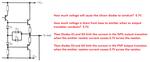
This is a opamp output voltage booster schematic but I can not understand how each part work ,if any one can analysis this circuit please explain it for me in detail.

2xxv_pp.jpg
 

It is a very simple audio power amplifier circuit with a differential input. You need to learn about the basics of transistors to understand how each part works.
 
It contains sections which are typical in an op amp. As Audioguru states, it has the differential input (long-tail pair).

The rightmost two transistors are a half-bridge. This resembles the final output stage of an op amp. The correct biasing comes from the section in the center (diodes, resistors, transistor).
 

It is a very simple audio power amplifier circuit with a differential input

I know it is a power amplifier I can't analyze center part of this circuit
 

An amplifier is usually destroyed if it is playing and the output is shorted because then the output current will become much too high. Diodes D3 and D4 were added to limit the maximum output current like this:
 

Attachments

  • amplifier current limiting.png
    amplifier current limiting.png
    44.7 KB · Views: 96
Status
Not open for further replies.

Similar threads

Part and Inventory Search

Welcome to EDABoard.com

Sponsor

Back
Top