Continue to Site

Welcome to EDAboard.com

Welcome to our site! EDAboard.com is an international Electronics Discussion Forum focused on EDA software, circuits, schematics, books, theory, papers, asic, pld, 8051, DSP, Network, RF, Analog Design, PCB, Service Manuals... and a whole lot more! To participate you need to register. Registration is free. Click here to register now.

How to calculate parasitic resistance and capacitance of an inductor theoretically

Status
Not open for further replies.

Elecemperor

Junior Member level 2
Joined
Apr 11, 2015
Messages
22
Helped
1
Reputation
2
Reaction score
1
Trophy points
3
Activity points
211
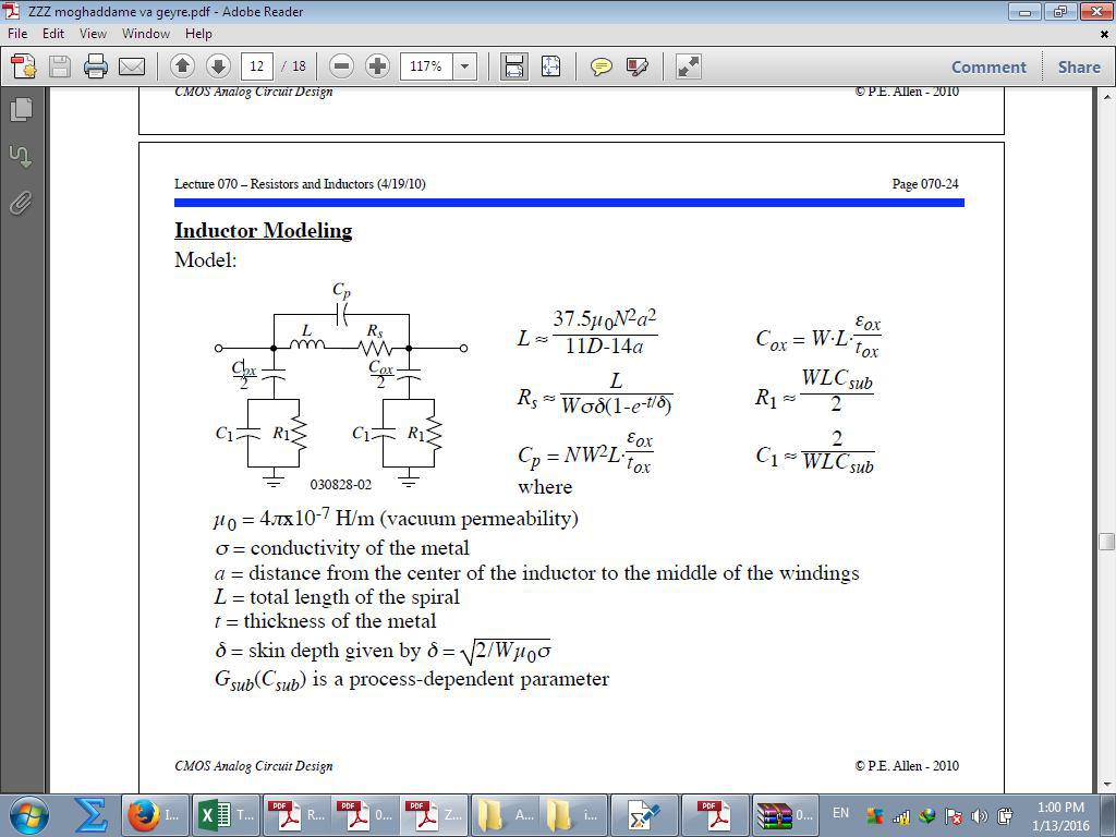
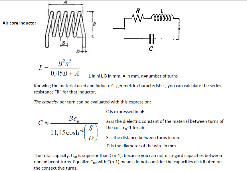
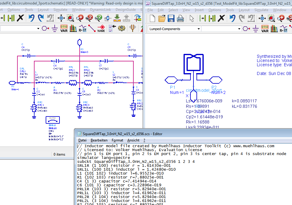
I am trying to provide an algorithm to design a distributed amplifier at 40GHz based on mere calculation for which I need to model the elements of my artificial transmission line as precisely as possible. I've found simple models to calculate the parasitic resistance and inductance of a capacitor, but I can't find the same formula for an inductor. I know how to measure the amount using Cadence, however, I'm looking for a mathematical expression consistent with my measurements.
Any help and insights would be greatly appreciated.
 

Obviously there's the DC resistance which you measure with an ohmmeter. This is likely to be very small, because an inductor operating at 40 GHz is likely to have few loops of wire.

Likewise capacitance between neighboring loops is liable to be very small.

Skin effect plays a part at high frequencies.

One wavelength at 40GHz is 1/3 inch. This approaches a point where component size can influence performance, although I don't know exactly how, nor what formula to apply.
 

Thank you for your reply. Yes, I know how to measure the DC resistance and all, and I've got estimations of all parasitic elements, but I'm looking for an exact calculational base for my measurements.
I've come across a model whose image I've uploaded, and I've found all the parameters in it except for Csub. I know it can be calculated by Csub=Ca*length*width + Csw*2*length, but the substrate capacitance per unit area (Ca) and the sidewall substrate capacitance per unit length (Csw) are still unknown to me. Does anybody know their values?
 
Well, it depends on the shape of the inductor that you have...

What I have found is the typical model for the inductor with series resistance, capacitance and the inductance for an air core inductor.


but the substrate capacitance per unit area (Ca) and the sidewall substrate capacitance per unit length (Csw) are still unknown to me. Does anybody know their values?

Not trivial to estimate this. We don't even have that one simple ground node as depicted in the equivalent circuit model.

Angelo Scuderi et al provide some useful equations for equivalent circuit modelling in "Integrated Inductors and Transformers" (CRC Press).

In this book, you will find : Rsub*Csub = epsr_sub * rho_sub (Pfost, Rein, Holztwarth 1996). However, when I tried to apply that for real world SiGe inductors with non-homogeneous substrate doping (EPI layer) that equation didn't work well.

My approach is to extract the equivalent circuit model parameters from EM simulated (or measured) inductor data.
https://muehlhaus.com/products/equivalent-circuit-model-fit-for-rfic-inductors

Thank you very much, volker@muehlhaus. The information was helpful, though I've found a seemingly more complete model with all the values in the book "RF Power Amplifiers" by Dr.M. Kazimierczuk. The results it yields are close enough to my estimations, so I guess it can help me work something out. And I have done EM simulations in HFSS, but because I had to look for a computational model, they were not sufficient for me. I just have to check their consistence with my calculations now.
I still have one more question left: When printing DC operating point for inductors in Spectre, three values of Csub are shown. Why are they three, and what is each of them?
 

I still have one more question left: When printing DC operating point for inductors in Spectre, three values of Csub are shown. Why are they three, and what is each of them?

I don't know your netlist, but for a center tapped inductor I would expect threee substrate branches in the model, so that we have three Csub elements. Two of them would be identical if the inductor is symmetric.


Image is from:
https://muehlhaus.com/wp-content/uploads/2014/01/modelfit.png
 
Last edited by a moderator:
Status
Not open for further replies.

Part and Inventory Search

Welcome to EDABoard.com

Sponsor

Back
Top