Continue to Site

Welcome to EDAboard.com

Welcome to our site! EDAboard.com is an international Electronics Discussion Forum focused on EDA software, circuits, schematics, books, theory, papers, asic, pld, 8051, DSP, Network, RF, Analog Design, PCB, Service Manuals... and a whole lot more! To participate you need to register. Registration is free. Click here to register now.

ATMEL AFE Chip question (ATM90E26)

Status
Not open for further replies.

hm_fa_da

Full Member level 5
Joined
Sep 16, 2003
Messages
287
Helped
10
Reputation
20
Reaction score
4
Trophy points
1,298
Activity points
3,217
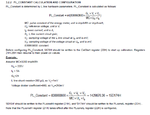
I am developing an Electricity single phase meter which uses ATm90E26 as AFE, there are different registers for gain and offset calibration in the chip, but in Constant configuration formula ( mentioned in m90E26 application note, page 10 ), i think it is wrong ! because it is based on parameters which i have to put in formula like VL and UL ... which are not exact and calibrated !
constant.png
the formula is:
int(838860800 x (GL x VL x VU) / (MC x Un x Ib ).

MC, Un and Ib are constants and no problem,

but VL and VU are sensitive to hardware which are not same in all devices and boards, all gain and offset calibrations are done to correct these Errors, so i think this formula should take numbers from the result of "after calibration" values not constants calculated by theoretical Voltage Divider Coefficient for example (like the application note sample) !

The device after calibration, shows Voltage and Current and phase angle true in other registers ! so KWh can be calculated by those values, and putting a constant number for frequency of CFx output blinking should be enough for Meter Constant setting !
but why the more and not calibrated parameters like Vl and Vu are required again ?!
 

Why do you think that VU and VL are theoretical values? Aren't they actually measured values?

By the way, you didn't quote the document where you copied the section.

- - - Updated - - -

Found out that you quoted the application note http://www.atmel.com/Images/Atmel-46102-SE-M90E26-ApplicationNote.pdf

Seems like VU and VL are nominal response factors, given by the shunt and voltage divider values.

The Voltage divider value (and current) is theoretical, it can not be calculated exactly because of electronic parts tolerance and that is why there are different registers for Gain and offset calibration in M90E26 chip !
and as you can see calibration process in the application note, it is done during real testings on Vn and Ib and then calibration registers are updated. then the chip calculates true Vrms and Irms.
this calibration process should be done in each board separately.
using nominal values for shunt and voltage divider which are not accurate (the reason all calibration processes are done) makes a not accurate imp/KWh rate result !
all my purpose is at this point.
for example, the Vu / Un is not an accurate constant value, this value is exactly calculated "after board calibration process".

anyway, when the device is calibrated and shows Vrms and Irms and phase angle true ( in dedicated chip registers ), so KWh can be calculated and i just should set imp/KWh value !
i don't understand why i should enter the not accurate Vgain (Vu/Un) and Igain (GL.VL/Ib) values again !
 

According to my understanding, VU and VL are nominal values and don't need to be accurate. Please review the explanation in the datasheet about the purpose of PL_Constant
PL_Constant is a threshold for energy calculated inside the M90E26, i.e., energy larger than PL_Constant will be accumulated in the corresponding energy registers and then output on CFx.
 
  • Like
Reactions: itssmk

    itssmk

    Points: 2
    Helpful Answer Positive Rating
According to my understanding, VU and VL are nominal values and don't need to be accurate. Please review the explanation in the datasheet about the purpose of PL_Constant

You are right according to the quoted sentence (for Energy accumulation it doesn't need to be much accurate) but if PL_constant be not accurate, the Blinking Rate of CFx (LED) meter will be not accurate too, so it won't be 3200 imp per 1 KWh .
and this makes problems, because one of the meter accuracy verification processes according to IEEE is to check the imp/KWh rate by external calibrated load and meter.
in this case the under test meter will output higher or lower than standard blinking rate of CFx on 1KWh load for example !

And also inside of the board, MCU reads the "Energy Registers in m90e26" which the value is proportional to PL_Constant ! the register includes number of output energy pulses generated.
i.e 3200 value in APenergy register means 1 KWh Forward Active energy, but if the PL_Constant be not accurate, 3200 pulses will not mean exactly 1KWh usage.
 
Last edited:

Hi,

I see two sorces of external hardware errors:
1) Voltage_divider_coefficient error
2) Line shunt resistor error.

In The example the nominal voltage divider rate is 880.
But maybe the true rate is 872.
--> so the true Vu = 220V/872 = 252.3mV --> use this value for the PL_Constant calculation

In the example the nominal shunt resistance is 200u Ohms.
But maybe the true resistance is 234uOhms.
--> so the true VL = 5A x 232uV = 1.16mV --> use this value for the PL_Constant calculation

***
I´m not familiar with your chip. But if I remember right (with other energy meter chips), then you first should calibrate voltage, then calibrate current.
If both calibration is correct you can calculate PL_Constant with the nominal values (no need for extra calibration), because the complete power calibration is already finished with U and I calibration.
Check on this. I´m sure there is a "calibration" section in the datasheet or in an application note.

Klaus
You are completely right !
there are registers for Voltage and current rms calibration, and i'm just getting confused on this point, these calibrations fix errors, so the chip calculates rms voltage and current true, the voltage calibration is like:
Vcal.png
But in the PL_Constant setting, it requires nominal and not accurate values !
according to the voltage calibration method, i think ( as you said ) calculate the calibrated gains manually and then insert it in PL_Constant formula. but finding exact VL and Vu is little complicated and should be calculated through final calibration values of each meter board not real shunt resistance or voltage divider rate measurement ...

Why does the DSP inside the AFE chip need gain values again ?! when Voltage rms and Current rms and phase angle are calibrated, so it can calculate KWh, so for PL_constant i should only enter the desired pulses per KWh, (imp/KWh) !

at first point i think, the application note is wrong ( at least at the example of setting nominal values in formula - seems true is to calculate gains through final calibration results of Vrms and Irms ) and next point, i just don't understand need of inserting gains in formula ! ( it can be obtained from the chip inside set and calibrated parameters ).
 
Last edited:

Hello,

I am using the same chip ATM90E26 on a custom board. The board is working fine , as there is proper communication between the IC and the micro-controller. I am able to read and write into register.
In the application note it is mention that frequency, phase angle and power factor parameters are not required calibration.
I am getting -
frequency -- 51Hz,
phase angle -- 337 and
power factor -- 0

I am following the calibration procedure as in the Atmel's application note:
http://www.atmel.com/Images/Atmel-46102-SE-M90E26-ApplicationNote.pdf
But all other register are having zero values. I am not understanding what is going wrong. Can someone please suggest me calibration procedure.

Thank you.
 

Hi,

maybe ther is no (valid) input signal,
or the gain values for voltage and/or current is not set properly.


If you need more help:
Connect valid an known (tell us) voltage and current signals
then read out all register values and post them.

Klaus
 

Hi KlausST,
Thanks for your response.
I am getting voltage at IC across the divider as 267mV. So i think there is a proper AC signals.

My Configuration is as follows.
Shunt 2m Ohm and LLine Configuration.

Software Configuration
REG_CALBR_START written 0x5678
REG_CHECKSUM1 ( 0x2C )- read and written back to same Register
REG_PL_CONST_HIGH (0x21) written 0x00DA
REG_PL_CONST_LOW (0x22) written 0x2E8B
REG_MODE_CONFIGURATION (0x2B) written 0x7422
REG_SMALL_POW_MODE ( 0x04 ) written 0xA987

After this LLINE_MEAN_ACTIVE_POWER ( 0x4A ) Register Value Read 5 times
and then METER_CMD_LLINE_MEAN_REACTIVE_POWER ( 0x4B ) Register Value Read 5 Times And accumulated values separately and find the compliment values for the same and written those offset values to METER_CMD_LLINE_ACTIVE_POWER_OFFSET (0x37) and METER_CMD_LLINE_REACTIVE_POWER_OFFSET ( 0x38 ) respectively.

REG_LLINE_CALBR_GAIN (0x23) written 0x1475
REG_LLINE_CALBR_ANGLE (0x24) written 0x0024
REG_ACTIVE_START_POWER_THRES (0x27) written 0x08BD
REG_ACTIVE_NOLOAD_POWER_THRES (0x28) written 0x08BD
REG_REACTIVE_START_POWER_THRES (0x29) written 0x08BD
REG_REACTIVE_NOLOAD_POWER_THRES (0x2A) written 0x08BD
REG_VOLTAGE_RMS_GAIN (0x31) written 0x5C3B
REG_LLINE_CURRENT_RMS_GAIN ( 0x32) written 0x5AA7
REG_SMALL_POW_MODE (0x04) written 0x0110 // to exit from Small Power Mode
REG_CALBR_START ( 0x20) written 0x8765 // to exit from Calibration mode


After that I have check the Register Values as below

0x42 :0x0000
0x43 :0x0000
0x44 :0x0AE1
0x45 :0x0AE1
0x46 :0xF801
0x48 :0x0000
0x49 :0x0000
0x4A :0x0000
0x4B :0x0000
0x4C :0x1405
0x4D :0x0000
0x4E :0x8588
0x4F :0x0000
0x68 :0x0000
0x6A :0x0000
0x6B :0x0000
0x6D :0x0000
0x6E :0x8176
0x6F :0x0000

From the above reading I understand that only frequency Register (0x4C) is giving the proper values.
Am I missing anything in the configuration flow. If yes, please suggest me the flow.
 
Hi,

please read back ALL registers, to be able to verify gain settings.. and all other settings.

Klaus
 

Status
Not open for further replies.

Similar threads

Part and Inventory Search

Welcome to EDABoard.com

Sponsor

Back
Top