Continue to Site

Welcome to EDAboard.com

Welcome to our site! EDAboard.com is an international Electronics Discussion Forum focused on EDA software, circuits, schematics, books, theory, papers, asic, pld, 8051, DSP, Network, RF, Analog Design, PCB, Service Manuals... and a whole lot more! To participate you need to register. Registration is free. Click here to register now.

1kW Flyback converter for battery charging

Status
Not open for further replies.
Regarding the 2 switch flyback, if you look at the Basso book equation 7-60B on page 615 (post #14 above)…this effectively shows that the voltage available to reset the leakage inductance of the transformer is….
Vin – Vout/[ns/np]

This is a negative value if “Vout/[ns/np]” is bigger than vin.

So what is the mechanism of leakage reset if the 2 switch flyback is continuously connected to an input voltage that is less than Vout/[ns/np]?
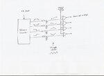
 

The useable duty cycle range of a two-switch converter is limited to 0.5, the condition applies both to forward and flyback operation. The voltage conversion ratio of the flyback converter is restricted respectively.
 

    V

    Points: 2
    Helpful Answer Positive Rating
Thanks, and as you know, even if one does restrict the D to <0.5, we still can't use the 2 switch flyback as an offline, single stage PFC'd converter.
 

Under steady state conditions, and nominal line/load conditions, yes. Not a robust design philosophy to ignore transient conditions and edge cases though.
What transient conditions are you referring to ?

Current mode controlled diagonal half bride is about as bullet proof as it gets.

- - - Updated - - -

So what is the mechanism of leakage reset if the 2 switch flyback is continuously connected to an input voltage that is less than Vout/[ns/np]?
No problem at all.
In fact I have developed two excellent applications where there is no secondary winding. Its just a diagonal half bride driving a gapped choke.
And both run continuously at full duty cycle maximum power, with no ill effects whatsoever.


More on this later if anyone is interested.
- - - Updated - - -

The useable duty cycle range of a two-switch converter is limited to 0.5, the condition applies both to forward and flyback operation. The voltage conversion ratio of the flyback converter is restricted respectively.

This is indeed true, 50% duty cycle is always the limit for half bridge diagonal topology.

However, the voltage conversion ratio is limited only by the flyback transformer ratio.
Flybacks are routinely used to generate tens of Kv from a low voltage battery source.
 
  • Like
Reactions: treez

    T

    Points: 2
    Helpful Answer Positive Rating
Thanks Warpspeed, I see your point, even if v(refelected) was bigger than vin it wouldn't be a problem, because the primary would just clamp at vin, and never start conducting into the secondary.....still beats me what the "applause" that Basso was talking about.
 

Even if v(refelected) was bigger than vin it wouldn't be a problem, because the primary would just clamp at vin, and never start conducting into the secondary....

The stored energy in the core + leakage inductance just recirculates back to the main input bus bulk capacitor. It a remarkable energy recovery system.

This is now how I test all my dc chokes and flyback inductors.

Fit the inductor to a half bridge diagonal driven by a function generator (set fixed at 50% fixed duty cycle).
Power the diagonal bridge from an 0-30v dc bench power supply via a large low ESR electrolytic.
Hook up a CT or Hall current sensor to measure inductor current, and watch it ramp up and down on an oscilloscope.

By adjusting the both switching frequency and dc supply voltage, and monitoring the ramp current on an oscilloscope, I have full control over both "on" time and inductor charging voltage.

All pretty straightforward, but the amazing thing about this is that I can ramp up to 30, 50, 80 Amps, but the 30v bench power supply only needs to supply an amp or two to do it.

After a big ramp up, (almost) all the stored energy circulates back to the dc bus capacitor, and the bench power supply only has to make up for losses. Mostly conduction loss in the diodes and mosfets.

This makes a really great inductor tester, I can safely run just about anything up to saturation and see where that is, as well as being able to measure the rate of current rise, and hence calculate the inductance.
Great for setting air gaps too.

Its all mounted in my "magic inductor test box", which only takes a minute or so to plug into CRO, power supply, and function generator, and its all set to go.
 
Very useful device, incredible post. Good job warpspeed.

I have seen devices like this before, but they were just a high current FET in series with the inductor. You needed a high current power supply for high current tests.
 

Thanks Warpspeed , treez, mtwieg, FvM, FlapJack for sharing your knowledge on my problem. If I use Flyback in DCM will the ripple current be a problem for battery charging, in a way will it affect the battery life.

If I use Flyback in CCM, then the system will be in Mixed Phase, so it is not an unstable system.

I also want to know that for voltage control using Flyback converter having battery at load, is it required to use an inner current loop using PI control.

Please correct me and guide me.
 

I would not be too concerned about a bit high frequency ripple into the battery, as long as its not huge. A low ESR electrolytic located right at the flyback rectifier should all but eliminate the problem.

Battery desulphators used with lead acid batteries deliberately do something very similar, and its actually beneficial !

Very sensitive equipment connected direct to the battery, such as Hi-Fi, radio receivers and such, may suffer if there are very fast spikes on the dc supply, but a fairly simple RF filter after the low ESR electrolytic should get rid of that fairly well.

Voltage mode control only uses one PI loop that compares battery voltage to a voltage reference. This holds true in either continuous or discontinuous operation.
There will also need to be a separate current limit circuit that takes over control from the voltage control loop. These do not operate simultaneously, its either one or the other controls the PWM.

With current mode control, there is always a slow outer voltage PI control loop, and a much faster inner peak current control loop. Current limit usually comes for free with this, and for several reasons its usually a better performing system.
 
  • Like
Reactions: Ravi_H

    Ravi_H

    Points: 2
    Helpful Answer Positive Rating
Thank you Warpspeed for your generous help for clearing my doubts.

1) I want to know about Flyback step-down converter operation. Does the mode of operation of flyback in CCM or DCM depend solely on the Magnetizing inductance value or is it dependent on the duty cycle.

2) I have seen that duty cycle for flyback is restricted to 50%. Will any damage to the system occur if by chance the duty cycle increases, say about 90% ?, cause in feedback loop the duty cycle can increase beyond 50%.
 

Ravi,
1) You design your inductor (primary) to have sufficient turns and core cross sectional area to support the operating voltage and frequency.
It's really no different to designing any type of transformer.
Faraday's law and all the related equations apply to flyback.

However, the inductance of the primary (and secondary) can be changed by fitting an air gap, and that is quite independent of the above Faraday number of turns calculation.

Bigger air gap produces a much faster current rise which will be needed for discontinuous operation. For continuous current operation the only change would be to reduce the airgap slightly which will increase inductance and slow down the rate of current rise and fall.

When it's all assembled and working, you can adjust the airgap to get it working exactly right in either CCM or DCM mode, or something that changes mode half way.

2) Usually a flyback is designed to use one output of a two output PWM chip, so the duty cycle is limited to 50% maximum. That allows up to 50% of the time for the core primary to charge up, and up to 50% of the time for stored energy to discharge into the secondary.

That is a pretty good way to do it, and probably results in the most efficient design for a flyback transformer. The turns per volt will end up being equal on both primary and secondary.

There is nothing stopping you using unequal time intervals primary to secondary, but its very rarely done that way with a transformer.

More or less than 50% max, is usually reserved for boost converters and buck boost converters which both work on the flyback principle, but use only a single choke winding not a transformer.

With the luxury of a secondary on a transformer, you can run more or less turns than the primary, get your output voltage higher or lower than the input voltage, and use a conventional 0% to 50% PWM chip.
 
  • Like
Reactions: Ravi_H

    Ravi_H

    Points: 2
    Helpful Answer Positive Rating
Ravi,


2) Usually a flyback is designed to use one output of a two output PWM chip, so the duty cycle is limited to 50% maximum. That allows up to 50% of the time for the core primary to charge up, and up to 50% of the time for stored energy to discharge into the secondary.

Hi warpspped:
Thanks for the Valuable and humble Reply.

I Just want to ask that what scenario follows in half bridge an full bridge.

how they charge and discharge when both the devices are on.. This is the basic Doubt.

- - - Updated - - -

Warpspeed, Really sorry about getting the name wrong
 

With flyback, the current in the primary only charges up the core in one direction for usually up to 50% of the time.

There is either only one mosfet, or two that turn on simultaneously in the case of the diagonal half bridge topology.
 
  • Like
Reactions: Ravi_H

    Ravi_H

    Points: 2
    Helpful Answer Positive Rating
I want to do something similar, but with 3 or 4 interleaved phases. I also want to be able to set the output power/duty cycle, and read back the output with an Arduino SPI or IIC. Can anyone point me to a suitable controller ? (This question has been asked elsewhere too)
14 < Vin <20, 14 < Vout < 18, Iout < 20A
 

you could use 4 interleaved coupled sepics for that if you wanted, if you don't need isolation.
or 4 interleaved LT8705's
 

This is drifting off topic from the original post, but here goes.

Its really difficult trying to synchronise multiple interleaved controllers to operate all together at the same frequency, with constant relative phase shift, and load share equally.
It becomes a nightmare jungle of parts.

A clean sheet of paper design starts to become attractive with multiple interleaved phases. If I was ever doing this again, I would probably use a master clock driving a Johnson counter with each phase generating its own triangle wave.
A single control voltage then controls all the PWMs together.
Here is an example of four phase quadrature operation with a common control voltage:

Interleavedpwm.jpeg
 

yes, and some controllers have a sync pin which you can literally just put a square wave into , and if you want 4 interleaved square waves one of the linear.com timerblox chips can do it for you...it also does 3 interleaved.

I have seen that duty cycle for flyback is restricted to 50%. Will any damage to the system occur if by chance the duty cycle increases, say about 90% ?,
High duty doesnt damage a flyback, as long as you watch over your reflected voltages and check theyre not to high etc.

The one topology that is limited in duty cycle is the 2 transistor forward converter ...it is limited to 50% max

Also the 1 transistor forward is limited to 50% if the reset winding has the same number of turns as the primary.

The active clamp is also limited in duty cycle...but this is more complicated as it has something to do with sudden increases in duty cycle causing overvoltages on the active clamp capacitor...so active clamp control chips often have maximum duty cycle setting pins.
 

Please can someone tell me, how to calculate the negative primary voltage of the flyback transformer, when the mosfet is off and the duty cycle is 40%. I have read that, it should be negative of the input voltage, when the duty cycle is 50%. But I'm getting more negative voltage than the input, atleast double of the input.

Because of this negative voltage, my voltage across mosfet drain to source is increasing.
 

negative primary voltage of the flyback transformer, when the mosfet is off

It's possible the snubbing network is not sufficient to handle the spike at switch-Off. It should be designed to absorb a momentary burst of current, equal to the Amperes flowing through the primary at switch-Off. The snubbing capacitor can charge to an overly high voltage, if it is too small a value.
 
  • Like
Reactions: Ravi_H

    Ravi_H

    Points: 2
    Helpful Answer Positive Rating
VOLTAGE ACROSS PRIMARY WHEN fet IS off is [VOUT * NP/NS]

However, if that value is above vin, then its wrong and you need to re-do
(this is for a 2 switch flyback)

when the fet first switches off the volts acorss the pri soars to vin because of the leakage L discharge

.
 
  • Like
Reactions: Ravi_H

    Ravi_H

    Points: 2
    Helpful Answer Positive Rating
Status
Not open for further replies.

Similar threads

Part and Inventory Search

Welcome to EDABoard.com

Sponsor

Back
Top