Continue to Site

Welcome to EDAboard.com

Welcome to our site! EDAboard.com is an international Electronics Discussion Forum focused on EDA software, circuits, schematics, books, theory, papers, asic, pld, 8051, DSP, Network, RF, Analog Design, PCB, Service Manuals... and a whole lot more! To participate you need to register. Registration is free. Click here to register now.

[SOLVED] RTC not acknowledging slave address

Status
Not open for further replies.

my_abousamra

Junior Member level 3
Joined
Nov 25, 2008
Messages
25
Helped
0
Reputation
0
Reaction score
0
Trophy points
1,281
Activity points
1,478
Hi there,

I'm writing a driver for m41t83 RTC IC and on AT91SAM7X (based on ARM7).

I'm trying to start communication with it over TWI (fast mode) and I have no response from the RTC (always get NACK).

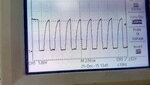
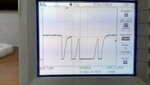
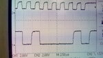
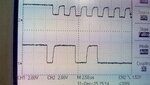
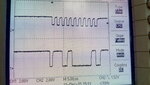
I don't know what might cause the problem. Attached here some photoes to clock and data wires on oscilliscope where I send the RTC address 0x68 after the start condition and send write bit but receive a NACK.

Also, please check the clock signal if it is valid because I suspect that it may cause some problems according to its shape
 

Attachments

  • clock.jpg
    clock.jpg
    3 MB · Views: 137
  • data.jpg
    data.jpg
    2.5 MB · Views: 157

SDA and SCL waveforms look like you have too high pull-up resistor values. To allow checking of signal timing, you should capture SDA and SCL with two oscilloscope channels.

You should also reduce the image size of the screenshots before posting.
 
The 0 to 1 transitions in the SDA waveforms are taking around 3 us to rise, hence there is no proper data to be clocked into the slave due to which you might be getting a NACK. And the clock on SCL isn't a proper square wave either.

@FvM
What are the standard pull-up resistor values for a I2C bus?
 
There's no standard value, everything depends on the total bus capacitance. I would consider 4k7 down to 1k.
 
I'm using 10K as pull up resistors soI will try to use lower resistors value like 1k5
 

This clock wave was generated from the controller and I don't know why its shape like that. anyway I will change the pull up resistors the try again
 

I guess, slow SDA and SCL rise time is mostly caused by using a 1:1 oscilloscope probe with typically 100 pF capacitance, waveforms probably look much better without probe connection. You may want to use a 10:1 probe and check again. Lower pull-up resistors would be preferred anyway.
 
Hi,

Please check if 0x08 is shifted one bit left to get 0xD0....

I saw some I2C address incompatibilities, some use the upper 7 bits but shifted one bit left, some use the upper 7 bits but AND with 0xF7.

Check binary bits: 0x68 ==> 0b 0110 100R, where R represents the rw bit
Some say it is ==> 0b 110 1000 R.

Klaus

Datasheet says that the device address is 0xD0 and I shifted it right to get the address 0x68 then the R/W bit

- - - Updated - - -

There's no standard value, everything depends on the total bus capacitance. I would consider 4k7 down to 1k.

lowering the pull up resistors to 1k5 doesn't solve the problem!
 

Hi,

Datasheet says that the device address is 0xD0 and I shifted it right to get the address 0x68 then the R/W bit

If the pullup doesn't help and the RTC doesn't acknowledge, then I still assume you don't use the correct address.
0b11010000 for write and 0b11010001 for read.

Show us the code and a scope picture of both SCL and SDA.

Klaus
 

Hi,


If the pullup doesn't help and the RTC doesn't acknowledge, then I still assume you don't use the correct address.
0b11010000 for write and 0b11010001 for read.

Show us the code and a scope picture of both SCL and SDA.

Klaus

This is the sending function

Code:
/* Send data to device */
void vTWI_SendData (uint8 u8DeviceAddress, uint8 * u8Data, uint8 u8DataLength)
{
	AT91S_TWI *pTWI = AT91C_BASE_TWI;

	/* load device address in write mode */
	pTWI->TWI_MMR  = u8DeviceAddress << 16 | AT91C_TWI_IADRSZ_1_BYTE << 8;

	pTWI->TWI_IADR = 0;

	/* start sending data */
	pTWI->TWI_THR = *u8Data++;

	/* decrement data length */
	u8DataLength--;

	while (u8DataLength)
	{
		/* wait for data to be sent to shift register */
		while( ( pTWI->TWI_SR & AT91C_TWI_TXRDY ) == 0 );

		/* continue sending data */
		pTWI->TWI_THR = *u8Data++;

		u8DataLength--;
	}

	/* wait for data to be sent to shift register */
	while( ( pTWI->TWI_SR & AT91C_TWI_TXRDY ) == 0 );

	/* wait for holding and shift register to be empty */
	while( ( pTWI->TWI_SR & AT91C_TWI_TXCOMP ) == 0 );
}

and this is how I call it

Code:
    uint8 data_to_send[2] = {0x00, 0x55};

    vTWI_SetClock(TWI_FAST_MODE);

// RTC_ADDRESS = 0x68
    vTWI_SendData(RTC_ADDRESS,data_to_send, 2);

and the plots as same as the previous and unfortunately I have one probe for this scope

- - - Updated - - -

Note that: if you checked the data picture of scope (consider 2 bits per square) you will find

START_BIT(0) ADDRESS(1 1 0 1 0 0 0) WRITE_BIT(0) NACK(1) STOP_BIT(0)
 

Hi,


Did you ever try to use:

// RTC_ADDRESS = 0xD0

KLaus

Sure, It was the first thing to try, Note that controller only allocate 7 bits for slave address in pTWI->TWI_MMR so assigning this value will ignore the most significant bit and the address will be 0x50 (which is not working too)

In addition, In RTC data sheet signal sketches, they show 0x68 plus I found BSD driver for this RTC and they use 0x68 as well

attached screenshot from the data sheetdata_sheet.png
 

Hi,

I can´t review the bit sequence,
neither from your code (because it´s not clear to me how it combines address, RW bit and ACK bit)
nor form your scope picture (because i have no relation between SCL and SDA)

--> try to find a second probe and show us an actual two channel scope picture

Klaus
 

Hi,

I can´t review the bit sequence,
neither from your code (because it´s not clear to me how it combines address, RW bit and ACK bit)
nor form your scope picture (because i have no relation between SCL and SDA)

--> try to find a second probe and show us an actual two channel scope picture

Klaus

hmmm,

I got another probe but unfortunately my scope doesn't support triggering the two channels simultaneously and I don't have logic analyzer!
 

You don't want to trigger on both channels, just record both channels simultaneously. I didn't yet saw a 2-channel DSO that wasn't capable of doing so.
 
You don't want to trigger on both channels, just record both channels simultaneously. I didn't yet saw a 2-channel DSO that wasn't capable of doing so.

I'm not so familiar with oscilloscope but I can only see the signal when the channel get triggered or it can't see any.

Now, I tried to send the RTC all address 7-bit address available from 0 to 127 (using loop) but I always received a NACK.

Note: signals seems now good with reasonable rising time after restoring default settings of the scope and reconfiguring it again.
 

Hi,

I can´t review the bit sequence,
neither from your code (because it´s not clear to me how it combines address, RW bit and ACK bit)
nor form your scope picture (because i have no relation between SCL and SDA)

--> try to find a second probe and show us an actual two channel scope picture

Klaus

Finally, I could make it.

Attached, A photo for the SDA, SCL in small scale and 2 other photos with larger scale for the start and the end of the communication
 

Attachments

  • dual end.jpg
    dual end.jpg
    2.7 MB · Views: 142
  • dual start.jpg
    dual start.jpg
    2.9 MB · Views: 144
  • full dual.jpg
    full dual.jpg
    3 MB · Views: 142

I see correct write address 0x68 but no acknowledge. There's possibly a hardware problem with the RTC, e.g. with the power supply.
 

Hi,

According timing information of the m41t83 data should change AFTER falling clock edge. With your scope picture they are very close.

Check if /RSTout is stable high.

Do you use SOX18 package? -->
* Did you connect 2,3,9, 16,17 to Vss?
* Did you connect 6 and 15 to Vcc?

Klaus
 

Status
Not open for further replies.

Similar threads

Part and Inventory Search

Welcome to EDABoard.com

Sponsor

Back
Top