Continue to Site

Welcome to EDAboard.com

Welcome to our site! EDAboard.com is an international Electronics Discussion Forum focused on EDA software, circuits, schematics, books, theory, papers, asic, pld, 8051, DSP, Network, RF, Analog Design, PCB, Service Manuals... and a whole lot more! To participate you need to register. Registration is free. Click here to register now.

designing a charge controller for hybrid system

Status
Not open for further replies.
thanks,
As what i have seen on net some other approaches are:
Keep the voltage across battery constant i.e:
if the panel voltage is increasing then controller will keep constant voltage at the load for this it will try to reduce the PWM(to reduce load voltage) and in-turn increasing the current.
If panel voltage decreases then PWM increases to maintain same voltage at reduced current.
How about this approach?
 

If panel voltage decreases then PWM increases to maintain same voltage at reduced current.
How about this approach?

If the panel voltage is decreasing....
And you further INCREASE the duty cycle, how is the current being reduced ?

All it will do is pull the panel voltage down, which further increases duty cycle, which pulls it down even more.
It will just lock up at continuous 100% duty cycle with the panel voltage and battery voltage both being tied solidly together.

When I first looked into all this, from all that I had read on the internet I believed the "perturb and observe" algorithm was the only effective method of MPPT .

Some very scholarly articles have been written on all this.

My first step was to get two identical solar panels, two power meters and two identical resistor loads set up to compare different approaches.
My Turnigy power meters recorded both amp hours, and watt hours, so over maybe a day I could do a back to back test of different algorithms and play around with some different ideas.

I was absolutely astonished to discover that all that is needed to keep right at the MPPT point was to keep the solar panel voltage constant. Nobody else does this, and I just cannot understand why nobody else has figured this out.

Its pretty easy to do that with just a buck regulator controlled by its own input voltage. It will adapt to put maximum power into ANY load large enough to more than fully load down the panel.

You can fit a potentiometer to tweak the panel voltage up and down under load, and see for yourself the power always peaks at the same solar panel voltage.
Its not critical either, a volt each way only drops power by maybe two, three or four percent, which is really nothing.
 
Thanks, for your reply
Starting with solar converter at first i need to design a buck converter could you please help me design it.
1)how to select switching frequency.
2)value of inductor.
3)value of capacitor
Solar vocc=20.7V
Vmpp=18V
Vo/p =14.4V to charge 12V 150ah battery.
 

Ok, couple of questions.

What is the power rating of the solar panel ?
The inductor will require a ferrite core with an air gap, do you already have any parts there that you think might be usable ?
 

power rating of solar panel=110W.


these are few i found one was in radio receiver but it has no air gap. other one in invereter:
core (1).jpg
core (2).jpg
core (3).jpg
 

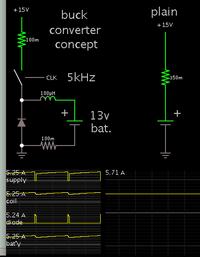
This simulation illustrates the concept of a buck converter, delivering bulk charge (left-hand schematic).

By operating at 100 percent duty cycle you can draw all (or almost all) the energy from a PV panel, continuously. This illustrates the point which you wanted clarified (post #17):

Therefore your charge controller input should be able to draw maximum continuous Amperes from the panel.Internally it may have a different waveform. That does not need to be at a constant level, but can be triangular which is typical in a buck converter.

For comparison, the right-hand schematic is direct connection of PV panel to a battery.


Notice that you need to minimize parasitic resistance, in all the places you can.

The inductor needs to be able to carry several Amperes, without saturation.
 
Thanks, for your reply
Starting with solar converter at first i need to design a buck converter could you please help me design it.
1)how to select switching frequency.
2)value of inductor.
3)value of capacitor
Solar vocc=20.7V
Vmpp=18V
Vo/p =14.4V to charge 12V 150ah battery.

Looking at the inductor requirement first, gapped ferrite is the usual thing to use, but as our voltage and frequency will both be quite low, a powdered iron toroid starts to look like an attractive alternative.

I used some free design software from the Micrometals web site to come up with a suitable design. Something like 250uH at 5 Amps for 20 Khz operation.
Micrometals suggest 70 turns of 20Awg wire on a T150-26 core.

That started me thinking.
Its a pretty ordinary type of thing, so I decided to look on e-bay to see what was available, both in a bare core, and already wound.
There are several that look like they may do the job, and at pretty low cost too.
Its hardly worth the trouble to wind your own.

Anyhow... There is this:
**broken link removed**

The size, number of turns (from the picture), and ratings all appear to come pretty close to the type of thing we need.
 

thanks,
But i just want to clarify with various design equations one goes through to find out inductor value. By suitably substituting in equations i could find out that i would require 402.5uf capacitor and 21.19192uH inductor considering 50Khz switching frequency. Although i dont want to spend time building one we get a readymade inductor here at our place.
But, i just want to know a bit of theory behind design equations.
Now switching frequency =50Khz because it seems that with decerasing frequency ripple content increases and with increasing frequency switching lossses increases for a MOSFET.But, for proper trade off b/w ripple and losses had to choose 50K.
so design equations are:
As panel o/p power =100W.
o/p voltage required=12V
I/p voltage maintained,Vmpp=17V
o/p current =(100/12)=9.2A(max).
let switching freq,Fsw=50K.
D,duty cycle=(12/17)=.7058(min)
dl=ripple current ,thumb rule =25-35percent of full load current,let dl=35%of (9.2A)=3.22
As L=(V)(ton/dI). here dI=ripple current
inductor value,L=(Vin-Vo)*D*(1/fsw)*(1/dl)
hence L=21.9192uH.
Inductor peak current=Io/p+dl/2=9.2+1.61=10.83A.
Ok i got these design equations But, substituting the values that you have mentioned i.e 20K,5Acurrent in the equations given above i got 54.798uH but, you got 250uH. Why these differences are the design equations correct?.
 
Last edited:

Inductor peak current=Io/p+dl/2=9.2+1.61=10.83A.

Can your PV panel produce 10.83A peak? Your earlier specs reported a much lower figure.

Although 12V is the nominal voltage of the battery, it will rise to 13V soon into a charging session, and could rise to 15V if you let it overcharge. I had my own backup power system for a few years, and I recall letting that happen with my batteries (it was really as a test, honest). At 15V the batteries are 'gassing', meaning bubbles are rising in the acid.

That is why we taper down the charging current as the battery approaches 14.4 V.
 

My figures, rated power of panel 100W at the standard 1Kw/Sq meter.

Real expected watts output in direct Sun usually about 80% of that.
Estimated output at MPPT point 17 volts about 4.7 amps = 80W.

Output of buck converter 12v
Estimated output current 17v / 12v x 4.7 = 6.66 amps

Switching frequency 20Khz = 50uS
On time of buck converter 12/17 x 50uS = 35uS
Inductor will have 17 - 12 = 5 volts across it during on time.
Rate of current rise 5v x 35uS divided by 250uH = 700mA
Peak to peak ripple 0.7A / 6.66A = maybe about 10.5%

Efficiency will probably end up about 90% so expect to see maybe 6 Amps max into a flat battery with a clear blue summer sky, decreasing as the battery voltage rises.

That is how I did it originally.
 
Hi,
As you had mentioned that if i have a solar panel than, i should go on loading the panel to find out max power delivered for different insolations.
And you also said that you obsereved that max power delivered is also at a particular panel voltage only(vmpp).
Now understanding that i need to keep panel voltage always=Vmpp.And that is what is max power point tracking.
There can be two approaches as i see here :
1)one should have a current sensor, voltage sensor and find power from panel at every instant vary the PWM such that max power is to flow.
Now say algorithm is tracking max power point then,at a particular irradiance software is increasing PWM to track max power point (V*I) but suddenly irradiance decreases due to which the present power point will be less than the previous power point hence as per algorithm the previous point is max power point & hence final PWM set will be =that for previous value.
This way there will not be exact tracking.
2nd approach is tracking this vmpp Now i will require only voltage sensor and i should always see that this voltage should be constant.
If irradiance decreases now what is the power will not be seen but it will see this Vmpp and is never bound to make error in setting max power point.
I think the second approach is proper though both are correct.
 

Another thing i want to ask is:
When battery is getting charged, simultaneously there should not be load drawn from battery right?
like the mobile battery we cannot use it when under charging.
I should also make a suitable arrangement to consider that thing also right?
 

Another thing i want to ask is:
When battery is getting charged, simultaneously there should not be load drawn from battery right?

I don't think that is necessary. It will only affect your rate of charging.
 

Can your PV panel produce 10.83A peak? Your earlier specs reported a much lower figure.
That is the inductor peak value implies : the current should not go beyond 10.38A else inductor will saturate which is undesirable for buck converter.
I had other doubt:
As we require MOSFET gate driver if using n-channel on higher side(mosfet is put before load)
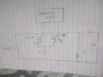
But i thought of modifying the circuit as shown below in diagram.
There i have used two n-channel MOSFET N1:will turn on during Ton time and N2 :will turn on during Toff time.Would the circuit below work as a buck converter?
buckcon.jpg
 
Last edited:

But i thought of modifying the circuit as shown below in diagram.
There i have used two n-channel MOSFET N1:will turn on during Ton time and N2 :will turn on during Toff time.Would the circuit below work as a buck converter?
I don't see how that can work.
The solar panel, inductor and load are always constantly connected in series.
All the mosfets do is connect and disconnect the capacitor which does nothing.

You can power a load while the battery is charging, load current just subtracts from the available charging current.

Just build a conventional buck regulator with N channel mosfet, and using the negative side of both solar panel and battery as common ground.
This definitely complicates gate drive, but it simplifies measuring solar panel and battery voltage to use as feedback to control the buck regulator.
 
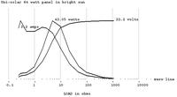
Here is my graph of PV panel output. I put my 64W panel in the sun and hooked up various resistors. I recall that it would push about 4A into a 12V battery. (Way under the advertised power, in agreement with Warpspeed's admonition.)

The Y axes plot voltage, current, power. The X axis is ohm load.


As you can see, maximum power occurs at some midway position for V & A.
 
Switching frequency 20Khz = 50uS
On time of buck converter 12/17 x 50uS = 35uS
Inductor will have 17 - 12 = 5 volts across it during on time.
Rate of current rise 5v x 35uS divided by 250uH = 700mA
Peak to peak ripple 0.7A / 6.66A = maybe about 10.5%
.

from post #30.
If i continuously need to track for vmpp depending on irradiance then,software should continuously vary the PWM which would increase or decrease the PWM and hence Ton time i.e if PWM icreases Ton increases and for a fixed inductor value ripple current increases and opposite happens in case when PWM decreases.Inspite of these could the best buck converter be made?
 

The first thing to realise is that the solar panel is a current source. If it is capable of putting out X amps, you cannot draw more than that from it without collapsing the voltage.
You will require a fairly large electrolytic capacitor directly across the solar panel, ahead of the buck regulator. Probably about 1,000uF should be sufficient.

The solar panel charges this capacitor at a constant current, but you can then draw intermittent pulses of much higher current, during the on time, the extra current being sourced by this capacitor.

By using a larger inductor that produces a lower ripple current, it makes the job this input capacitor has to do a bit easier.

The peak to peak ripple current remains pretty constant. If its ten percent at full load, it will be twenty percent at half load, and one hundred percent at one tenth of full load.
Below that the current through the inductor pulses on and off, its not continuous.

So for what we are doing, a large inductor that creates a lower ripple current has some benefits.

While it is common to design buck regulators that always run fully loaded with fairly high ripple current (20-35%) for us it is a big disadvantage because we will be operating over a very wide range, right down to no load at all sometimes.

The inductor cannot be made too large, 1% ripple current would be even better, but its just not practical, the inductor would be enormous.
So use your calculations to ball park a minimum inductor requirement, then find something at least that value.
 
thanks,
i made gate driver circuit to drive the high side mosfet
Actually this is not the circuit i built the circuit is as below:
mosdriver.jpg
now in this circuit you can see that the pin 5 of tlp250(optocoupler) i.e ground of that ic is connected to source of mosfet.
but i tried with two conditions:
1)connecting as it is.
2)connecting pin 5 to ground of supply.
And hence got two results:
i am inscribing the video clipping:
this is video of connecting pin 5 to ground of supply.
https://drive.google.com/file/d/0B9S6uuNt7m4ObXp4MDVneXhXUFk/view?usp=sharing

- - - Updated - - -
And in other video where i have connected as it is:
led is always lit up and when pwm is applied,only during ton intensity of led increases during toff intensity reduces but led doesn't go off.
But still it's recommended that the connections should be as it is.
Wont the load get continuous supply if i do so?
 

supplying gate drive to a buck regulator poses some rather unique problems.

The gate driver dc power supply needs to be completely isolated.
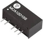
Simplest solution is to just buy a 12volt to 12volt isolated power module, and connect the floating 12v output to pins 5 and 8 of your TLP250.

These modules are available in a whole lot of different input and output voltage ranges, and are more or less readily available from e-bay for a few dollars.
The part number usually gives a pretty strong clue to the input and output voltages, here is a 12v to +/- 15v output example:

Isolatedps.jpeg

https://www.ebay.com/sch/i.html?_fr...0.Xisolated+1w.TRS0&_nkw=isolated+1w&_sacat=0
 

Status
Not open for further replies.

Similar threads

Part and Inventory Search

Welcome to EDABoard.com

Sponsor

Back
Top