Welcome to our site! EDAboard.com is an international Electronics Discussion Forum focused on EDA software, circuits, schematics, books, theory, papers, asic, pld, 8051, DSP, Network, RF, Analog Design, PCB, Service Manuals... and a whole lot more! To participate you need to register. Registration is free. Click here to register now.
Hello guys. Can someone help me with this experiment? i am trying to use scr triggering in order to produce larger output power at the load with 24 volts output dc and 220vrms input AC THANKS!!
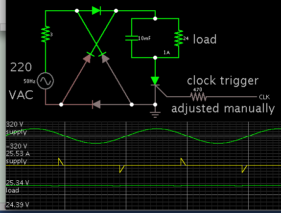
Perhaps this simulation resembles what you have in mind? Seems like it ought to be a great idea. No transformer.
The scr conducts a small fraction of the mains AC waveform. To obtain just 24W, it must draw large current for that time. This may even be more Amperes than the house wiring can provide.
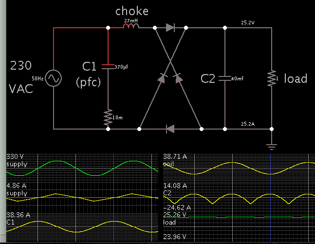
It is possible to reduce current drawn from mains AC, by putting a choke inline. C1 is needed for power factor correction. You draw just a few A from mains, theoretically.
Your load must be constant 600W for the output voltage to come out right.
You can still include your switching devices, if that is your decision.
In case you only want to use scr switching, see this recent thread.
It's not the best way to do it, but well feasible following classical SCR control schemes. The essential point is to have a sufficient large storage inductor on the DC side along with a free wheeling diode. The uncomfortable point is that you get small conduction angles and respectively high peak current (same magnitude as Idc) on the mains side.
A reasonable design would place a transformer (e.g. 230 to 30V) on front of the controlled bridge. As already mentioned in the similar threads, you only need two SCRs and two diodes.
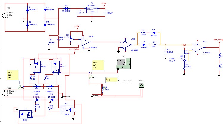
From the schem of the top post it would be interesting to see how you are closing the loop, presumably with a micro, as no error amp is seen. Also, hope those 4n25's aren't getting overvoltaged.....I think you would need a more robust scr drive solution
If you need 600W at the output, you will need a 700W transformer at mains frequency. The biggest advantage will be the isolation from the mains. But the transformer will just add to bulk. To filter the large peak currents on the mains side, you will need high value capacitors and inductors. SCR makes it look simple and attractive but may be simply not worth it. You need to balance the 700W transformer with mains isolation vs jumbo capacitors and chokes without mains isolation.
Mains peak current drops by factor of 8 when using a transformer. Storage inductor characteristic I²L doesn't drop so much, current stays the same and L can be reduced for same current ripple, may be by a factor of two.
In any case it's legacy power electronics, bulky but simple and reliable. Fully educated engineers should at least learn about it.
This site uses cookies to help personalise content, tailor your experience and to keep you logged in if you register.
By continuing to use this site, you are consenting to our use of cookies.