Continue to Site

Welcome to EDAboard.com

Welcome to our site! EDAboard.com is an international Electronics Discussion Forum focused on EDA software, circuits, schematics, books, theory, papers, asic, pld, 8051, DSP, Network, RF, Analog Design, PCB, Service Manuals... and a whole lot more! To participate you need to register. Registration is free. Click here to register now.

Designing an Avalanche Transceiver (457kHz) from Scratch? Where to start?

Status
Not open for further replies.

elektrotechnik

Junior Member level 1
Joined
Jul 31, 2013
Messages
19
Helped
0
Reputation
0
Reaction score
0
Trophy points
1
Activity points
198
Hi all,

I am looking to improve my circuit design, PCB prototyping and fabbing skills and I am looking for a project to take up some of my time this winter. I am looking to build my own avalanche transceiver from the ground up, and I was hoping that I could come here for some direction.

I am looking to replicate something similar to the Backcountry Access avalanche transceiver shown here: **broken link removed**. I am not looking to build something with this level of direction sensing and output, but rather something more barebones.

I only found one post on the forums that specifically talked about the design of a 457kHz transmitter, and that is found here: **broken link removed**.

From what I gleaned:
For the receiver:
I would suggest a JFET, source follower then a second filter, possibly a ceramic IF filter then a high gain stage. Also consider rectifying the received signal before measuring it. At the moment it appears you are trying to digitize the RF which plays no useful purpose and makes it far more complicated. The transmitted signal is pulsed, if you average the pulse levels and use that as your measurement it will be less susceptible to interference and give a more stable reading.

For the transmitter:
In the transmitter, you really want a clean sine wave at the output and as much RF delivered to the antenna as possible within the limitations of the battery life. If you use the digital divider method, apply filtering to the signal to remove harmonics before amplifying it and use a simple keyed supply amplifier using a single transistor. Match it's output to the antenna with a pi network or tapped coil to maximize energy transfer and also minimize the chance of causing interference. Incidentally, to cover 50m (metres) range reliably you should only need about 5mW output power.

I also found this block diagram from Colorado EE (ecee.colorado.edu/~ecen4610/expos13/accubeacon_CDR.pptx
):
block.JPG

This is the transmitter circuit from the powerpoint. Is this a good place to start? How do I choose the Crystal Oscillator? What is confined to the Micro?
transmitter.JPG

I don't have a huge background in hardware design, so I am pretty lost in this thread.

If I am looking to build a basic barebones 457kHz transceiver, what should be my first steps?

Thanks for your help!
 
Last edited:
For the receiver, a ferrite rod antenna works pretty well on the broadcast band (550Khz to 1500 Khz) and should make a very compact and efficient self contained antenna at 457 Khz.

Ceramic resonators with a centre frequency of 455 Khz will be broad enough to cover 457 Khz but also significantly reduce out of band interference.

There are plenty of "complete radio receivers on a chip" to choose from, many are designed for radio control of models, garage door openers and such. But should be pretty easy to adapt for 457 Khz by just using the IF and detector stages.

The transmitter could just be a modulated single transistor crystal oscillator feeding the same ferrite loop antenna as the receiver.
 

The frequency needs to be accurate so I think my approach would be to start with a higher frequency quartz crystal oscillator and divide it down to 457KHz. That makes it easier and cheaper to find suitable crystals. The resulting frequency can be filtered using standard ceramic resonators as Tony suggests. If you start with 7.312MHz and divide by 16 it gives 457KHz and would also be a nice frequency to use for an MCU clock oscillator.

The transmiter would use the frequency directly and the receiver can use it 'zero IF' through a mixer or better still, use a quadrature signal from the frequency divider to create I and Q signals for digital demodulation.

I'm not sure how the Backcountry unit is made so directional but I would be careful using a single ferrite loop antenna because it would make the transmit signal directional. For rescue purposes, you want the signal to be omni-directional so it can be detected anywhere in the vicinity.

Brian.
 

If you can find a standard frequency crystal that will divide down to exactly 457 Khz that would certainly be very convenient.

But you do not gain anything in accuracy by doing so.
A 50 ppm crystal would be about +/- 25 Hz at 457 Khz

At 4.57 Mhz a 50ppm crystal would be +/- 250Hz so frequency division does not really improve accuracy.

As the receiver bandwidth will probably need to be be several Khz wide for speech transmission, there is a fair tolerance for a bit of carrier frequency error.

An efficient antenna at that frequency is very big problem, and really there is no other practical choice other than a ferrite rod.

While it will certainly be directional, the null point will be along the axis of the rod and be very narrow. If the rod is vertical it should work well in all directions except straight up and down.

And if you are directly over the victim, the distance surely cannot be too great in that situation.

One thought just occurred to me.
For optimum transmitter efficiency the ferrite rod antenna needs to be tuned exactly resonant for highest efficiency.
One possible way to do that, might be to make the rod energising coil part of a power oscillator, and phase lock that to a separate low power crystal oscillator.

In other words for the transmitter, build a high power phase locked loop with a nice powerful VCO of which the rod antenna is an integral part.
 

... wasn't inferring a divider would increase accuracy, only that it would probably be necessary to use quartz and higher frequencies than 457KHz are easier to source.

I'm not sure making the ferrite and coil a VCO tuning component, simply because relatively large size in a small housing would make it prone to outside effects, for example hand capacitance. De-tuning it as a transmiting antenna will reduce radiated power which is less serious than going off frequency. I would make it resonant but tap the feed point to get best impedance matching and use the 475KHz source to drive it directly. Electronically, it's probably simpler than a PLL.

I wonder if the Backcountry unit just uses relative received strength as the direction indicator and uses two antennae (probably ferrite rod based) at 90 degrees to each other to give it directivity. It would be interesting to open one up.

I think they are probably very narrow bandwidth, they send an ID signal, probably using OOK or FSK but I don't think they can send or receive voice.

Brian.
 

... simply because relatively large size in a small housing would make it prone to outside effects, for example hand capacitance. De-tuning it as a transmiting antenna will reduce radiated power which is less serious than going off frequency.
That is the whole reason for using a phase locked power oscillator.
It will self tune the tank circuit to exact resonance, and correct any drift in tank resonance caused by external or internal detuning.
Its the accurate crystal reference that it phase locks to that provides a stable output frequency.
 

Thanks Tony, to explain, I think the first PLL I designed was for a stereo decoder back in 1968, I know how they work :smile:
I was considering that either way would require a crystal derived reference but given that the output power is maybe 10mW at most, it would be easier to simply amplify and drive the antenna. I was giving emphasis to functionality and cost over efficiency.

I was thinking of the 'crossed ferrites' antenna theory for direction finding and wonder if it could be applied to transmission as well as reception. It might overcome the TX directivity but I'd hate to work out the resulting field lines. It's something I have never experimented with.

Brian.
 

Thanks for the responses, fellas.

For reference, the powerpoint that I referenced has a photo of an unpacked Tracker DTS Transceiver (I think). It's on Slide 71 here: ECEE Colorado.edu Transceiver Design

You guys seems extremely knowledgeable. My bachelor's degree is in EE, with only about 1 year of applicable experience in the field. I make an effort to teach myself something knew every day in the hardware realm and was wondering if you have any resources (books, blogs, websites) that you have used along the way.

Tony, you mentioned:
A 50 ppm crystal would be about +/- 25 Hz at 457 Khz
At 4.57 Mhz a 50ppm crystal would be +/- 250Hz so frequency division does not really improve accuracy.

Does this mean that the transmitter is sending a modulated 457kHz signal at 25Hz? So, the carrier signal is 25Hz with a 457kHz modulated signal to be received?
 

No, it means that a crystal marked " 457 KHZ" would be within 25 HZ of that exact frequency. Your transmission must be within the band that the rescue receiver is tuned to else they will not receive your signal.
For a rescue beacon such as one of these there would be a detailed specification, so different manufacturers equipment would be working to a common standard. If you get the full specification then the equipment design gets simplified. i.e. it will do the minimum required.
Frank
 

I was thinking of the 'crossed ferrites' antenna theory for direction finding and wonder if it could be applied to transmission as well as reception. It might overcome the TX directivity but I'd hate to work out the resulting field lines. It's something I have never experimented with.
Diversity reception, where more than one antenna or receiver is employed is an often used technique, its particularly useful for radio microphones used within buildings, where there can be "dead spots" due to strong reflections and signal cancelling. As a performer walks around a stage signal levels can vary dramatically from place to place.

In this application two crossed ferrite rod antennas could be used, and if this is a pulsed beacon, it could radiate alternately on each antenna when in transmit mode.

For reception, there would be two separate receivers, and the receiver developing the strongest received signal would automatically be chosen to do the receiving.
This system should also provide some very useful redundancy for circuit failure.
 

This gadget has built in LED indicators for direction over a 75 degree angle and a middle LED for 'straight ahead' so it must use the relative strengths of the two ferrites to find the middle position. It might be possible to do it with one receiver and switch between antennas, it would save on components and to some degree ensure equal gain in both sense directions.

Brian.
 

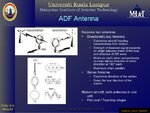
One method of radio direction finding is to use two antennas.
One is traditionally a vertical dipole that is omni directional.
The other is a fixed or movable loop antenna.
As the source moves around the loop antenna the amplitude changes, but so too does the phase relative to the dipole.

The problem with just using the loop by itself is that the null axis produces a 180 degree ambiguity. By comparing the phase to a dipole it resolves that, giving a single direction.
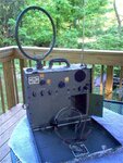
Here is some state of the art 1942 WW2 technology:

RDF.jpg

This may also work with crossed ferrite rods, but I am not absolutely certain of that.
The traditional open loop radio direction finding antenna is usually air cored, a ferrite rod grossly distorts and concentrates the magnetic field. What effect that has on the phase versus physical orientation I do not know.

Feeding both signals into identical limiting amplifiers, such that the outputs will be constant amplitude 457 Khz square waves, the phase difference (0 to 360 degrees) should reflect the azimuth of the source.

This principle is used in aircraft radio navigation aids, where a pointer gives the relative heading of the radio source without the 180 degree ambiguity.

RDF2.jpg
 
Last edited:

Status
Not open for further replies.

Part and Inventory Search

Welcome to EDABoard.com

Sponsor

Back
Top