Continue to Site

Welcome to EDAboard.com

Welcome to our site! EDAboard.com is an international Electronics Discussion Forum focused on EDA software, circuits, schematics, books, theory, papers, asic, pld, 8051, DSP, Network, RF, Analog Design, PCB, Service Manuals... and a whole lot more! To participate you need to register. Registration is free. Click here to register now.

[SOLVED] Simple voltage detect circuit: Switch 1 when 0.6V and Switch 2 when 2V.

Status
Not open for further replies.

Tuppe

Member level 2
Joined
Oct 22, 2011
Messages
46
Helped
2
Reputation
4
Reaction score
2
Trophy points
1,288
Activity points
1,789
Hello!
I need to tap in some extra functionalities to resistor divided buttons.
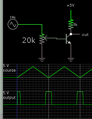
Normally I have 5V:
0.6V when I press button 1
2V when I press button 2

I need to switch separate transistor for both buttons. The imput impedance also has to be high so that I don't mess up the internal voltage dividers and cause wrong buttons presses.

I thought this was a simple problem, but after 4 hours of trying to achieve this, I'm stumped and I have to ask for help. I have zener diodes, op amps, mosfets, bjts etc. at my disposal.

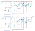
One of my solutions was to:
1. Flip the polarity so I have 0V referenced to 3V and 4.3V for button 2 and 1 respectively.
2. Have mosfet triggered with 3V, which is bypassed using 3.3V zener, which changes the mode to button 2.
I didn't get it to work. Any method is fine for me. I'm used to being Arduino n00b so I could solve this using Attiny85, but I really think this could be solved using proper engineering of basic discrete components.

Thank you for reading!
 

Hi,

Using window detectors and level shifting outout op amps you could have one detect approx 0.6V window and get approx. logic level 5V from comparator op amp placed in series on output of window detector op amps, and the same for the 2V - make it a window. This would involve a total of 6 op amps and 12 resistors (+ 2 to 6 resistors more if you feel need to place op amp output resistors).

If on the other hand you need 0.6V and 2V outputs, maybe a diode clipping an output to about 0.7V or lower and three diodes in series to get about 2.1V, maybe. If you have any adjustable 1.25V voltage references, one of those for the 2V.

Does sufficiently high resistor value in series with transistor bases not drop enough voltage and create input impedance?
 

Hi,
Using window detectors and level shifting outout op amps you could have one detect approx 0.6V window and get approx. logic level 5V from comparator op amp placed in series on output of window detector op amps, and the same for the 2V - make it a window. This would involve a total of 6 op amps and 12 resistors (+ 2 to 6 resistors more if you feel need to place op amp output resistors).
Hmm, that sure works but I assumed that there would be a simpler way to achieve this. If it's 6 op amps, I really have to go with a microcontroller ADC. I wonder how the people did this in the 70s if voltage detection needs 2 op amps. Making voltage references for all of those would be hell.
I just noticed that I actually have 6 buttons in the network, which must not interfere when picking up the voltage: 1.0V; 1.6V; 2.3V; 3.0V; 3.6V; 4.3V.
Do you think that MCU is the only simple way to get those 3.0V and 4.3V picked up from there? That complete system would need like 20 op amps if it was fully done using discrete components!?

If on the other hand you need 0.6V and 2V outputs, maybe a diode clipping an output to about 0.7V or lower and three diodes in series to get about 2.1V, maybe. If you have any adjustable 1.25V voltage references, one of those for the 2V.
I actually fine with any signal of the event so that I can switch on transistor. But I think I can figure that out.

Does sufficiently high resistor value in series with transistor bases not drop enough voltage and create input impedance?
Probably. Those buttons are divided by 10k resistors, so I need to be well in the +100k input impadances when I get the signals.

Thanks for the tips!
 

Maybe this can work for you. This requires just one dual opamp. The circuit in the blue box only simulates your 5V, 2V and 0.6V switch activated levels.
 

Attachments

  • v_switch.png
    v_switch.png
    45.3 KB · Views: 132
Last edited:
  • Like
Reactions: Tuppe

    Tuppe

    Points: 2
    Helpful Answer Positive Rating
A plain transistor can do the job, at least for the low voltage you named (1V).

Effective devices for the task are ones that abruptly turn on and off. The goal is that a slight difference in signal causes an abrupt change in output. Therefore as discrete devices we try diodes and transistors (because they contain a PN junction).

9550548600_1450205342.png
 
  • Like
Reactions: Tuppe

    Tuppe

    Points: 2
    Helpful Answer Positive Rating
Since you require >100k input impedance, the circuit can be modified to buffer the sampling voltage. You could still get away by using one quad package or two duals.
 

Attachments

  • v_switch1.png
    v_switch1.png
    25.5 KB · Views: 117
Last edited:
  • Like
Reactions: Tuppe

    Tuppe

    Points: 2
    Helpful Answer Positive Rating
A single IC, the 3914 dot-bar display driver, can detect 10 different volt levels. Its power supply needs to be higher than 6.8V, according to this article:

https://www.electronics-tutorials.com/devices/lm3914.htm

If you're lucky, its transition levels make a one-to-one correspondence with your choice of volt levels. If not then you must do some level shifting, or amplifying, etc.

Post #6 recommends a buffer op amp. That could simultaneously provide gain, to multiply your incoming voltage so it covers a wider range.
 
  • Like
Reactions: Tuppe

    Tuppe

    Points: 2
    Helpful Answer Positive Rating
Hi,

My suggestion was over component heavy - bad idea, on the other hand I am not certain the LM3914 would be a suitable device for this purpose, the buttons apparently are spaced out 1.0V; 1.6V; 2.3V; 3.0V; 3.6V; 4.3V, or seen as differences then 0V +1V, +0.6V, +0.7V, +0.7V, +0.6V, +0.7V - the ten comparator trip levels in the 3914 are separated by a resistor ladder made up of 1Ks (according to the datasheet I have at least), and besides which the slow transition from output to output up and down designed for "nice looking" LED switching with no off moments may be not ideal for the purpose, but maybe that only happens in bargraph mode and not in dot mode.

The suggestion of biasing transistors, or the dual op amp design seem better, or what Tuppe said about using the ADC on the MCU.
 

slow transition from output to output up and down designed for "nice looking" LED switching with no off moments may be not ideal for the purpose, but maybe that only happens in bargraph mode and not in dot mode.

I have made several voltmeters with the 3914. As you say, each transition lights 2 led's momentarily. It happens in dot mode, going up or down. This reduces room for 'play' in the space allotted to incoming signal levels.

Nevertheless the IC is an all-in-one unit, and adjustable, so it seems as though it could be adapted to the purpose. By expanding its range to match the separation between levels (0.6 or 0.7 V). Add a potentiometer to adjust the minimum threshold. Etc.
 

Maybe this can work for you. This requires just one dual opamp. The circuit in the blue box only simulates your 5V, 2V and 0.6V switch activated levels.

Wow, thanks for the design! I didn't expect full solution for the problem, this seems more like paid membership.

I wasn't able to reproduce that in LTSpice (which we use in school), maybe due to component variations(I used LT1001 and general purpose NPN/PNP). Is that TinaTI?
I will try to reproduce that design somehow so I can probe it around and see what it's doing.

I had to go with Attiny for the solution due to time, size and complexity constraints(I also had to add 3rd button), but these solutions are definitely something that I find useful to learn with. I've had my 1.5 years of EE bachelor's and I still cannot understand what is even happening there, not to mention to design that kind of circuitry out of my head!
I need to check into these designs more, thank you for the solutions everybody, I think I learned more in this topic than 1 month in the school!
 

Status
Not open for further replies.

Part and Inventory Search

Welcome to EDABoard.com

Sponsor

Back
Top