Continue to Site

Welcome to EDAboard.com

Welcome to our site! EDAboard.com is an international Electronics Discussion Forum focused on EDA software, circuits, schematics, books, theory, papers, asic, pld, 8051, DSP, Network, RF, Analog Design, PCB, Service Manuals... and a whole lot more! To participate you need to register. Registration is free. Click here to register now.

Charge pump and single pulse creator, how to?

Status
Not open for further replies.
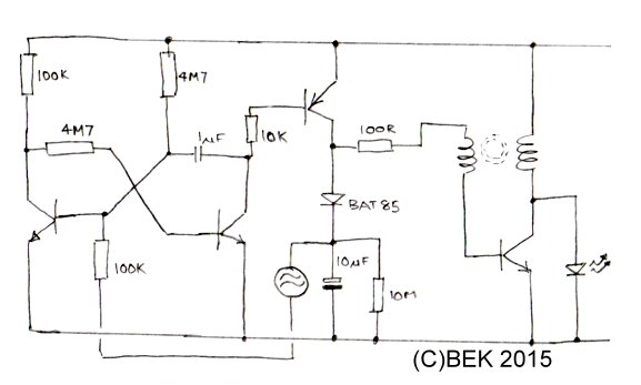
It should flash the LED for no more than about 1 second then it should go off completely and the circuit then draws no current. I suspect what is happening is the voltage in the transformer secondary (base side) is too high and it is enough for the transistor to maintain oscillation by itself when the bias is removed. Try removing turns from the secondary winding and see if that fixes it. Maybe the difference in the core I used is responsible for the extra feedback you are seeing. If all is well, if you short the emitter and collector of the PNP transistor, the LED should stay lit and it should go out as soon as you remove the short.

Brian.

No, I think you got it the other way round. What I mean is this:

With the original schematic, When I vibrate it (an only when I do so, not at other times) the LED flashes. But the joule thief is not blocked after a few vibrations, as it should.
It is blocked at all times when no vibration. But it is not deactivated after a few vibrations as it should.

As I see it this is a sign that the 10uF never charges.
I have tried it with a single 10nF instead and no discharge 1M resistor at all and it worked ok. After a few vibrations the oscillator is blocked. Of course there war no discharging resistor then and I had to short circuit the cap leads to discharge it manually.
But it does not work with the 10uF in place.

Any ideas?
 

Hi,

Maybe a good way to confirm what you may be seeing re the 10uF capacitor is with an oscilloscope, not sure betwixt or other people enjoy esp-like capability for esoteric "remote viewing" and sensing abilities :)
 

ESP would be useful ;-)

What you are describing is the timing circuit working as it should to produce the pulse but not allowing enough 're-arming' delay before it can be used again. Ideally you need a monostable circuit that draws no power but I don't think you will find one, especially working from 0.9V supply.

I do not have the 'prototype' with me at the moment to experiment but I suspect your problem is not the component values but leakage in the 10uF capacitor causing it to discharge too quickly. This would explain why the 10nF works as it is probably not electrolytic and would have lower self leakage current. In an ideal situation, the capacitor would only dischage through the resistor in parallel with it so the timing can be controlled by adjusting the values. Running electrolytics at low voltage is prone to problems, I suspect because of insufficient voltage to fully polarize the dielectric. In this circuit it would never have more than about 0.3V across it (supply - Vbe) unless the switch was held closed and even then it would only slowly rise to supply level. You could try a different type of 10uF capacitor to see if the leakage is lower, that might work. If you stay with 10nF the resistor across it would need to be unreasonably high in value, several hundred M to achieve the best time constant.

Please try this: I can't guarantee it will work but it's worth a try,
1. change the 10uF to a smaller value, try 100nF non-electrolytic, connect 10M in parallel with it.
2. connect the 10uF capacitor from the collector of the PNP transistor to 0V.

What I'm trying to do is make the trigger charge the 10uF instead and let that determine how long the oscillator runs for. A brief pulse when the switch closes will turn the PNP on and rapidly charge the 10uF, allowing bias to the oscillator stage. It doesn't fix the problem but it makes the selection of pulse timing components a little easier.

Brian.

Thanks very much Brian
Capacitor leakage explanation seems very reasonable, having in mind that the electrolytic I used is 16V and several years old.
Indeed the 10nF capacitor required more than 100M resistor across it (100M was not enough).
Thanks very much for all the help, it is a really amazing circuit that despide being simple, draws very little average current.
Perfect for the intended purpose.
Thanks once again!
 

Here's a new version to try. I added a low current monostable and an active 'inhibit' to prevent re-triggering too soon:


It works like this - the oscillator and PNP switch works as before but the first two transistors form a monostable circuit. In 'idle' state, the collector of the first transistor is low and the second transistor is high (keeping the switch OFF). When the first base is pulled low, the monostable changes state until the 1uF capcitor discharges then it returns to idle condition again, during this time the PNP switch is ON and the LED lights. When the PNP switch is ON, it charges the 10uF capacitor through the diode (must have low Vf) and raises the voltage across it too high to retrigger the monostable again. When back in idle state, the 10uF capacitor slowly discharges through the 10M resistor until it is close enough to zero to be useful as a trigger voltage source again.

1uF sets the pulse duration
10uF/10M sets the inhibit time.

It works fine on 0.9V but I found if I increased the supply to more than about 1.5V there was a tendency for the oscillator to run by itself. This is because the diode and capacitor 'close the loop' in the base side of the transformer and keep the bias running in the oscillator transistor. If your does that, the only simple solution is to reduce the turns on the secondary winding to drop the gain a little.

An interesting side effect of the inhibit circuit is if you keep the switch closed (unlikely in real life) it turns the monostable into an astable circuit and the LED will flash at inhibit rate. If all is well, that should be > 5 seconds or so. I used the same transformer as the previous design but this time I had an oscilloscope to hand so I could see the oscillator runs at ~53KHZ. The values I used were just components I had to hand, it worked with them but they are not critical. The NPN transistors were all BC548s. At very low voltages it isn't stable but the prototype still functioned at 0.59V !

You have permission to use the picture - please don't edit the little credit out of it ;-)

Brian.
 
  • Like
Reactions: neazoi

    neazoi

    Points: 2
    Helpful Answer Positive Rating
Here's a new version to try. I added a low current monostable and an active 'inhibit' to prevent re-triggering too soon:

Brian.

This is an interesting modification!
I am not sure if it worths the extra current drawn continuously by the multivibrator or the complexity of the circuit. Well not complex though, but more components needed anyway. The thing about the current is more important.
 

Not a multivibrator - it's a monostable. I measure the current in idle state as:
8uA at 0.9V
11.9uA at 1.2V
14.5uA at 1.5V

Brian.
 
  • Like
Reactions: neazoi

    neazoi

    Points: 2
    Helpful Answer Positive Rating
Here's my Mk3 version.

Using the same UV LED (Vf = 3.3V) it gives a bright flash at 0.9V supply with a 'just works reliably' supply voltage of 0.65V. I tried it up to 1.5V but not higher, it should be OK up to about 2V before the LED starts to draw it's own current.

I salvaged the ferrite core from a broken CFL, it seems to be used quite commonly in many different types but I do not have it's specifications or part number. You can get a slight increase in brightness by adding a 100nF capacitor from the junction of the 100R resistor and transformer to ground but it probably isn't worth fitting and it could risk the circuit self-biasing, in other words not shutting down after it has been triggered. It was OK for me but make sure it stops drawing current after a few seconds if you add it to your build. Increasing the 1M timing resistor will make it take longer to re-trigger but don't drop it below about 220K as it pass enough current to turn the first transistor on whenever the switch is closed.

Brian.


Hi Brian and merry Christmas!
Finally, I found out why my results were different than yours in this version of the circuit. You assumed a continuous charging pulse for the capacitor, whereas the vibration switch I use (pin inside spring) cannot provide such a pulse for so long duration.

Indeed when I replace the gravitational swith with a normal switch and close it, the led shines for about 2 sec or so then goes off.
The switch I suse just can't close for so much time.

Any ideas what other kinds of vibraswitch can I use for the purpose? I have seen a type that has a dual ball inside instead of a pin/spring, will that do better?
I do not want to use a mercury switch of course...
 

Merry Christmas Neazoi!

Try the circuit in post #66, the monostable only needs a very short pulse then the feedback capacitor takes over to maintain the current to the output stage. It should also inhibit re-triggering for a while because the charge on the 10uF capacitor has to leak through the parallel resistor before it will generate a new trigger pulse. It triggers by pulling the base of the first transistor to low potential, when that happens, the 10uF charges up until the monostable times out so the trigger voltage is too high to work again.

Brian.
 
  • Like
Reactions: neazoi

    neazoi

    Points: 2
    Helpful Answer Positive Rating
Merry Christmas Neazoi!

Try the circuit in post #66, the monostable only needs a very short pulse then the feedback capacitor takes over to maintain the current to the output stage. It should also inhibit re-triggering for a while because the charge on the 10uF capacitor has to leak through the parallel resistor before it will generate a new trigger pulse. It triggers by pulling the base of the first transistor to low potential, when that happens, the 10uF charges up until the monostable times out so the trigger voltage is too high to work again.

Brian.

Thank you Brian, I am trying this now.
Since I do not have the bat85 diode I wonder if I could even use a germanium , eg 1n34, for even a lower voltage drop
 

The 1N34 is specified to have a maximum Vf of 1.0V at only 5mA so it may not work as well as you expect when you consider the supply may only be 0.9V - but it's worth a try. The spec is worst case, in most situations it will work but the BAT85 has a maximum Vf of about 0.37V under the same conditions. The bigger problem with germanium may be the leakage current though. Again it's worth trying because the leakage path through the diode isn't directly to ground so it may not be as important as would first seem.

Brian.
 
  • Like
Reactions: neazoi

    neazoi

    Points: 2
    Helpful Answer Positive Rating
The 1N34 is specified to have a maximum Vf of 1.0V at only 5mA so it may not work as well as you expect when you consider the supply may only be 0.9V - but it's worth a try. The spec is worst case, in most situations it will work but the BAT85 has a maximum Vf of about 0.37V under the same conditions. The bigger problem with germanium may be the leakage current though. Again it's worth trying because the leakage path through the diode isn't directly to ground so it may not be as important as would first seem.

Brian.

Thank you very much Brian.
It would be helpful if you could suggest an SMD equivalent for this diode if you have some time, since the end product will be SMD based.
 

BAT46 (available in various SMD packages with single or dual diodes).
or try this link:
or the data sheet attached. The important characteristic is Vf, it may be specified at different currents but in that circuit it isn't constant and probably doesn't exceed about 10mA anyway.

Brian.
 

Attachments

  • sg2114.pdf
    1 MB · Views: 55
  • Like
Reactions: neazoi

    neazoi

    Points: 2
    Helpful Answer Positive Rating
BAT46 (available in various SMD packages with single or dual diodes).
or try this link:
or the data sheet attached. The important characteristic is Vf, it may be specified at different currents but in that circuit it isn't constant and probably doesn't exceed about 10mA anyway.

Brian.

Hello Brian and have a happy new year!
I was wondering why is the diode needed? Can't the pnp charge directly the capacitor?
Also, if I use an alectrolytic for the 1uF, which way should I connect it (plus/minus)?
 

Happy new year to you and your familiy Neazoi.

The diode is needed to prevent re-triggering, if there is voltage across the capacitor the monostable will not trigger when the switch closes. Without it, the charge will leak through the oscillator transistor B-E junction and may also prevent it from stopping oscillating. It may be worth experimenting with the diode connection, I didn't try it myself but in theory the voltage across the LED could be used instead. If it works, it would also have higher voltage (~3V) to work from so an ordinary silicon diode may work instead of a Schottky type. If you want to try, move the anode side of the diode to the top of the LED. Please measure the voltage across the capacitor and make sure you use one with high enough voltage rating, it should be less than 5V but switching transients may make it a little higher.

I wouldn't recommend an electrolytic for the timing capacitor for two reasons, firstly, the polarity may reverse as the monostable 'flips' and secondly because it needs to have low leakage and with such a low supply voltage a normal electrolytic may not have sufficient voltage to fully polarize, it may leak too much.

Thinking of things leaking - just over 1,000mm of rain fell here in December and everything is flooded!

Brian.
 
  • Like
Reactions: neazoi

    neazoi

    Points: 2
    Helpful Answer Positive Rating
If you want to try, move the anode side of the diode to the top of the LED.
I guess, with this mod, the PNP collector will only be connected to the 100R and to nowhere else?
Thinking of things leaking - just over 1,000mm of rain fell here in December and everything is flooded!
Ah yes, I heard it in the news yesterday! I seems to me the EISCAT, HAARP or similar projects are busy these years, unless it is all because of the bad CO2...
I hope you are not into big trouble with the flood!
 

I guess, with this mod, the PNP collector will only be connected to the 100R and to nowhere else?

Correct! It should only be the bias supply to the oscillator. Although it may seem intuitive to add a capacitor to ground, it would introduce the risk of the oscillator self biasing itself. If it did that, after starting it, the feedback could keep it running by itself when the bias was removed.

World weather has gone crazy, I'm at 52.5 North (you are at about 39) and yesterday there were people in tee-shirts playing on the beach here. Normally the temperature would be around 0C and instead it was 15C. It has rained every day for about 6 weeks but amazingly, last night it stopped and about 1,000 locals and visitors assembled for a midnight party and fireworks on the beach. More rain today though and no signs of it ceasing in the near future. :thumbsdown:

Brian.
 
  • Like
Reactions: neazoi

    neazoi

    Points: 2
    Helpful Answer Positive Rating
Status
Not open for further replies.

Similar threads

Part and Inventory Search

Welcome to EDABoard.com

Sponsor

Back
Top