neazoi
Advanced Member level 6
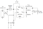
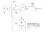
I am trying to fool the thing a bit, This is an incomplete schematic.
UPDATE
I think that this page https://courseware.ee.calpoly.edu/~dbraun/courses/ee307/F02/02_Sales/section02_bruce_sales.html explains well what a solution could be.
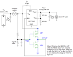
I am also posting the final schematic. The only power drawn by the battery is the leakage of the off-state mosfet and the internal leakage of the EN pin of the ic. I guess it would be in the uA scale.
What do you think of it?
") of T = R ohms * C in Farads ( and then tweak the results that don't ever seem to pan out in real world application!)
of T = R ohms * C in Farads ( and then tweak the results that don't ever seem to pan out in real world application!)