Continue to Site

Welcome to EDAboard.com

Welcome to our site! EDAboard.com is an international Electronics Discussion Forum focused on EDA software, circuits, schematics, books, theory, papers, asic, pld, 8051, DSP, Network, RF, Analog Design, PCB, Service Manuals... and a whole lot more! To participate you need to register. Registration is free. Click here to register now.

Intelligent Highway Street Lighting System

Status
Not open for further replies.

Eshal

Advanced Member level 1
Joined
Aug 29, 2012
Messages
470
Helped
16
Reputation
32
Reaction score
15
Trophy points
1,298
Location
Nowhere :)
Activity points
5,149
Hello to all experts,

I have been given a project as described in the subject of this thread and I have found **broken link removed** this resource over the internet.

You can see there is a schematic in the given link which is also shown below
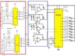
FLYFQWXI52CWVYS.jpg

In this schematic, he has used two ICs of LM339 one is connected with solar cell and other is connected with battery.

My first question is:
Do I need to use both for this project? Or anyone?


And then he has connected 4 amplifiers to the pins (p1.0, p1.1, p1.2, p1.3) of the microcontroller. I have asked the author of this article via pm about these amplifiers. He replied these are LM339 quad comparator.

My second question is:
What are those LM339 IC's (blue) and what are these LM339 IC's (red) because if both are same then (means a single IC) both have same components connected to them.


Best regards,
Princess
 
Last edited:
Your diagram has 3 separate schematics which can be seen as 'building blocks', for you to use or not, depending on what your design requires, what is your power source, etc.

They may need a lot of adjusting of values, positions, etc., in order to build them into a working project.

- - - Updated - - -

The lefthand schematics appear to monitor voltage levels for a battery (or PV panel).

The righthand schematic reads input signals from 4 comparators. I surmise it sends PWM to the led's, because it has a crystal oscillator attached.
 
  • Like
Reactions: Eshal

    Eshal

    Points: 2
    Helpful Answer Positive Rating
The comparator in red are meant to display a kind of bar graph showing the PV level and battery level. So you may chose not to implement them
 
  • Like
Reactions: Eshal

    Eshal

    Points: 2
    Helpful Answer Positive Rating
My power source is solar panel. So what amendment should I do in order to work it? Kindly help with this diagram. What should I remove from it?
What I understand up till now is that I need 2 ICs of LM339 one is marked in red and other is marked in blue as shown in attachment in post#1. Right?
 

I agree with post #3, the led's are a bar graph.

The 339 (left-hand schematic) contains 4 comparators. It is conceivable these are the same comparators in the right-hand schematic. (Although they have extra components attached at the inputs, these might be for a different project, with the same concept.)

You must examine volt levels as the led's turn on and off, because the voltage must be sufficiently high and low to activate the inputs on the 89s52 controller.

If all power comes from one source, then perhaps you only need one 339.
 

Personally, I would forget those diagrams as they are not directly relevant to street lighting.

If by 'intelligent' you mean the lights turn on and off according to ambient lighting conditions, what you need is a light sensor, maybe a comparator, a delay mechanism and a power switch. If the lights are battery powered, you can use the output of the PV as the light sensor as well as a charging source. The delay is necessary for two reasons: 1 it prevents flickering as the dark/light threshold is reached and 2. it stops the lights reacting too quickly if for example a bird flys over the sensor. A delay of at least several seconds is advisable and maybe as much as several minutes.

My own PV driven lighting uses the output of the PV cells to sense the light level and uses the voltage to 'hold off' a MOSFET power switch to activates the lights. PV output voltage is not proportional to the light falling on it so they are difficult to use for light level measurement but as a light or dark indicator they are ideal.

Brian.
 

Personally, I would forget those diagrams as they are not directly relevant to street lighting.

I presume, the circuit intends more than a simple twilight switch. There are three light barriers which may have the purpose of sensing traffic activity.
 

I received this message from the author,
Hi Princess,

Its alright, no one gets everything the first time. Lets make it simple.

As you may have seen in the schematics, there are three LM339 Comparator IC's. Lets name them:

1. Let the name of the one connected with Solar Cell be LM339-Solar.

2. Let the name of the one connected with Battery be LM339-Battery.

3. Let the name of the one connected with microcontroller be LM339-Micro.

You may have also seen in the LM339 datasheet that each IC is made up of Four comparators each with 2 inputs and 1 output.

It is a 14-pin comparator IC,

1. Pin 12 - ground

2. Pin 3 - Vcc

3. Pin 1,2,13,and 14 - outputs

4. Pin 4 to 11 - inputs

Now look at the schematics carefully -

In LM339-Solar, All output pins are connected to LEDs (These LEDs indicate the intensity of ambient light on Solar Cell), input pins 5,7,9,11 are connected a resistor network and input pins 4,6,8,10 are connected to a Solar cell via 4.7k pot and resistors.

In LM339-Battery, All output pins are connected to LEDs(These LEDs indicate the remaining battery charge levels), input pins 5,7,9,11 are connected to a resistor network and input pins 4,6,8,10 are connected to a battery via 4.7k pot and resistors.

In LM339-Micro, See the schematics very carefully and notice the connections of all the pins, its easy to identify everything well. All output pins are connected to microcontroller, out of its Four comparators, the inputs of three are connected to IR led and receiver diode pair (refer the schematics carefully for proper connection) and the input of fourth comparator is connected to an LDR.

I hope this will sort out all your queries.

All the best.
 

I want to know what can we do for only vehicles. Means street light should glow only when vehicle passes. Not for human or animal passing. Any Idea?
I think we need to use sampling or any advance technique for this. Right?

Idea please.
 

Look at differences between the things that should operate the lights and thing that should not. For example:

direction of travel,
speed of travel,
size of the object passing by,
does it have it's own lights turned on, (presumably it would if street lighting is needed at the time)
does it perturb a magnetic field?

Also consider the placement of the sensors, especially if the street lighting doesn't operate immediately. LED is OK but some fluorescent (SOX, Sodium etc..) take a while to reach full brightness.

Magnetic based sensors are probably most reliable for distinguishing vehicles from animals and people.

Brian.
 

magnetic based sensors? I have never heard about them before. Can you elaborate? And how they can distinguish between vehicles and other living things?
 

Are the living things where you live made of metal, or giving off magnetic fields, like cyborg animals or something? How do the living things get through metal detectors without setting off an alert? Are the living things made of flesh and blood, and the cars made of metal, maybe? They mostly are here.
 
  • Like
Reactions: Eshal

    Eshal

    Points: 2
    Helpful Answer Positive Rating
In Romania maybe.... I worked for a while in Timisoara :-D

It works on a similar principle to metal detectors but using a coil of wire buried under the road surface. As a large metal object like a car passes over it, the magnetic field around the coil is disturbed. You detect the change in current through the coil.

Brian.
 
  • Like
Reactions: Eshal

    Eshal

    Points: 2
    Helpful Answer Positive Rating
If a person having his toolbox (contained metallic components) passes over the road then magnetic field around the coil is disturbed. Then what? Then person would be treated as a vehicle. What do you think?
 

Depends on the street, an L.A. motorway or a small town main road? How big is the toolbox, how small is a scooter/moped?

I think the lighting system should be configured to either respond to a signal over a threshold value to avoid false triggering when the person with the toolbox walks past (Why wouldn't a person need to enjoy/use this system of street lighting, with or without a toolbox at night?), or be designed to turn on the street lights when an object bigger than a cat/dog passes within range - like the "Watch your speed" type indicators that use some sensor to detect motion/speed, or an outdoor alarm system using PIRs that turns on a floodlight.
 
  • Like
Reactions: Eshal

    Eshal

    Points: 2
    Helpful Answer Positive Rating
In the UK, they are typically square coils about 1.5m each side so they are relatively immune to small objects. It does depend on the size and speed of the metallic object passing over, at faster speed it will detect smaller objects. Here they are used to trigger a camera to record and detect a license plate number, then another detector some distance away will do the same so exceeding the average speed can be used to issue speeding tickets.

"Watch your speed" detectors use doppler shift at microwave frequencies to detect instantaneous speed.

Brian.
 
  • Like
Reactions: d123 and Eshal

    Eshal

    Points: 2
    Helpful Answer Positive Rating

    d123

    Points: 2
    Helpful Answer Positive Rating
OK. I am getting your both point of views. Here is a video in the below given URL. In this video some students of university have made the same project and in the last part of this video a professor asks them how they can distinguish between living(animals, human) and non-living(vehicles, scooter). Then they replied which I don't understand. Kindly watch the video and understand then tell me how they will do this.

[video]www.instructables.com/files/orig/FKI/YYVY/I3VI1MD0/FKIYYVYI3VI1MD0.avi[/video]

PS: The video is attached below the heading of "Conclusion" and above the heading of "Step 1: Connect the LDR sensors"
 

I tried but the audio is so bad it was difficult to understand. I think they were saying it had to do with the speed the object was travelling but that doesn't make sense. To detect speed you need to use Doppler techniques or two sensors. There is not enough space in their demonstration to use Doppler and in any case you can't use several Doppler sensors in such a small space, they would interfere with each other.

I suspect they use magnets under the toy vehicle or they used an IR beam between the lamp posts. You can see they are arranged opposite each other across the road. Breaking an IR beam will tell you something is there but not what it is. The time the beam is broken for also cannot be used reliably because it can't distinguish between a small slow moving object and a large fast one. It can be done more reliably, although not with certainty, with two parallel IR beams. The time between one beam being broken and the other will give a speed indication and the time both are broken for gives an idea of the size of the object. I think their demonstration may be to show the principle rather than a practical method though because if they used IR beams they would almost certainly be visible to the camera.

Brian.
 

I am very much agree with you betwixt. Sir, you are right. They just showed principle not practical method. Yes they have used sensors across the road.

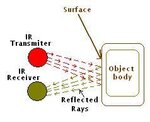
What if we use IR sensor on the same side of the road. Like when a car will pass then IR beam from transmitter would be transmitted towards the car body then reflect back to the IR receiver on the same side.

But when a person or animal passes then IR beam will not reflect to the receiver. Hence we can distinguish between car and human or animal.

But when a bike passes then I don't think reflection can take place because there not a solid regular sheet on the bike which could reflect the beam back to the receiver on the same side.

See the image below for clearification.
IR_theory.JPG
 

It sounds good in theory but you would quickly find out why opto-reflective switches generaly only operate over distance of a few mm. There are several problems, the main one is that you need a very powerful IR LED to get enough range. A normal IR LED has a fairly narrow radiation pattern, most of the light is radiated forward. To detect the reflection from an object, the 'mirror' would have to be positioned so it bounced the beam back to the sensor and with most vehicles the body shape would deflect the beam at other angles and miss the detector. Another problem is rain scatter, it makes the wanted reflection weaker and also gives a background 'noise' from random reflections in the rain drops.

There is another possible method that you could consider, checking the weight of the vehicle. It isn't as crazy as it sounds, what you do is fix a flexible pipe (like a hose pipe) across the traffic lane. One end is sealed and the other has a pressure operated switch on it. As the vehicle drives over the pipe, it crushes it and reduces it's volume which makes the internal pressure rise and operate the switch. This is the method used for counting vehicles for statistical analysis, like working out traffic flow at junctions but the switch could be used for triggering the lights instead.

Brian.
 

Status
Not open for further replies.

Similar threads

Part and Inventory Search

Welcome to EDABoard.com

Sponsor

Back
Top