Continue to Site

Welcome to EDAboard.com

Welcome to our site! EDAboard.com is an international Electronics Discussion Forum focused on EDA software, circuits, schematics, books, theory, papers, asic, pld, 8051, DSP, Network, RF, Analog Design, PCB, Service Manuals... and a whole lot more! To participate you need to register. Registration is free. Click here to register now.

Interrupt Exits in 89s52

Status
Not open for further replies.

gauravkothari23

Advanced Member level 2
Joined
Mar 21, 2015
Messages
640
Helped
5
Reputation
10
Reaction score
4
Trophy points
1,298
Activity points
6,922
HI all again.....
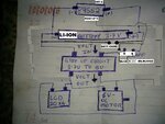
i have a very small issue regarding the circuit. circuit diagram has been attached.
my only problem is that when i connect my 5v charger to charge the battery the 89s52 exit the interrupt (INT-0) automatically. why is it so. when i connect my charger where is the interrupt being triggered to make 89s52 exit.
and also sometimes if it does not exits the interrupt while charger is connected... then after i remove my charger from the circuit.... i am not able to exit it even manually.... 89s52 shows 4.10v.. but still does not exits the interrupt.
 

Attachments

  • CIRCUIT new.jpg
    CIRCUIT new.jpg
    768 KB · Views: 74

8051's are extremely susceptible to electrical noise and fluctuations. They always go haywire. There is a chance when you are connecting the charger, its creating noise. Have you tried using an electrolytic cap in Vcc pin?
Datasheet says its "official" operating voltage is 4.0V to 5.5V @ 24MHz. In 3.7V it can loose its current vector and skip the smooth program instructions. I had these experience a lot. Lately I had to remove interupts. :bang:

yes i have connected a 4.7uf cap between +3.7v and gnd. it works perfect. the battery am using is 3.7v li-ion battery....so i get the peak voltage of 4.2v.... and at 3.7v i am using a auto recharge circuit..... so i think low voltage won't be an issue for me....
Anyways..... thanks for your reply....
 

Hi,

just reading the posts:

Datasheet says its "official" operating voltage is 4.0V to 5.5V
--> minimal votage is 4.0V

yes i have connected a 4.7uf cap between +3.7v
--> so 3.7V is out of specification.

89s52 shows 4.10v..
--> even 4.1V is near the lowest specified voltage. A short - even for microseconds - voltage drop may cause problems.

i have connected a 4.7uf cap
--> The microcontroller works in the MHz range. So the VCC capacitor must be able to be low ohmic in that frequency range. An electrolytic capacitor sure is not. What type of capacitor is it?

Klaus
 

Hi,

just reading the posts:


--> minimal votage is 4.0V


--> so 3.7V is out of specification.


--> even 4.1V is near the lowest specified voltage. A short - even for microseconds - voltage drop may cause problems.


--> The microcontroller works in the MHz range. So the VCC capacitor must be able to be low ohmic in that frequency range. An electrolytic capacitor sure is not. What type of capacitor is it?

Klaus


Here is the image of capacitor i have used.....
 

Attachments

  • 1447419472741-1317406092.jpg
    1447419472741-1317406092.jpg
    1 MB · Views: 62

What Li ion charger controller you are using?? Some chargers uses "trickle" charge technique to charge batteries. That will cause a lot of noise.
Is your INT0 pin is taking some signal input? Are you sure the signal voltage is absolutely stable?

As what Klaus said, maybe you are pushing the limit of minimum power supply. Can you use step up output to power the controller too?

i am using 7805 ic to charge the battery.
int 0 pin is connected to power using 10k resistance and on button press it is shorted to GND.

yes i can use the step up output to power the controller too but in that case the battery also starts self charging.... as you can see the circuit...

- - - Updated - - -

and step up converter also consumes a lot of current.... so to avoid that and for longer battery life i am using this type of circuit.
 

i am using 7805 ic to charge the battery.

You mean you are not using any Li ion charger IC, just the 5V regulator, and that 5v is fed to the battery directly??? This way you might blow up your battery. Li ion's are not so easy to charge. They need to follow proper charging technique. A simple 5v regulator won't suffice. Charging ICs like MC34673, MAX1737m, MC34673, etc. are needed. They follow a charging algorithm. These might also solve the glitch when you connect your regulator.

Have you connected a capacitor as shown in the datasheet at the output of the regulator?

yes i have connected a capacitor on output.... and even also i have attached one charging protection circuit to the battery.
so still do i need to change my IC's or 7805 regulator will work...
 

CIRCUIT new.jpg

Try a diode between controller and battery, also you can put a low value current limiting resistor.
 

if i use a diode as shown in circuit by you..... from where will yhe controller get power
 

1. Try to simulate the same circuit with three 1.5v alkaline batteries in series. Then connect the charger (not to recharge them. Just to see if the low voltage of Li ion is causing any problem).

2. Try disconnecting the step up circuit or the mosfet (for the moment) and then connect - disconnect the battery charger to see if that problem still occurs. If not, then for sure, you need to look at the power management process in your circuit, as you have two different power sources, but connecting to the same rail.

3. As per the block diagram you posted, it seems you have connected the charger's +ve terminal with the battery and the step up circuit. I don't know what's the actual arrangement is, but if that is a hard wired connection, then your charger will get confused while charging the battery, as it have to monitor the battery's status and supply the right voltage and current for charging. That power (from regulated charging controller to the battery) cannot be shared with any other circuits.

4. If, in your diagram, the 'BATT-CHRG' terminal is fixed 5V (7805) then it would't be much problem. Although you will require a charging protection circuit between the terminal and the battery. And if the terminal itself is the output of the charging protection circuit, then it will not work.

Can you explain / post what charging protection circuit you are using?
 

3. As per the block diagram you posted, it seems you have connected the charger's +ve terminal with the battery and the step up circuit. I don't know what's the actual arrangement is, but if that is a hard wired connection, then your charger will get confused while charging the battery, as it have to monitor the battery's status and supply the right voltage and current for charging. That power (from regulated charging controller to the battery) cannot be shared with any other circuits.

my charger(+) is connected only to battery, 89s52 and mosfet source pin and not the step up circuit.... only GND is common to all.... when interrupt is triggered... the pin from 89S52 gets low and activated the mosfet gate pin and then current is drained to step up circuit.... and when off key is presses from keypad.... 89S52 enters idle mode and sets the mosfet gate pin to high due to which current stops flowing to step up circuit.

i am using a samsung original battery which has a inbuilt protection circuit...
i have placed a 4.7uf capacitor between 89S52 and battery cap(+) to battery(+) and cap(-) to battery (-). which i think has solved my problem....
earlier whenever i attach my charger the 89S52 exits interrupt automatically.... but after placing the cap it works well... but still i am not confident about the results that if it is a proper circuit or not...
so placing a capactor is a good idea or something weird can happen...
 

i have placed a 4.7uf capacitor between 89S52 and battery cap(+) to battery(+) and cap(-) to battery (-). which i think has solved my problem....

So there's the problem.... 3.7V battery, which gives peak(stand by) around 4.2v, runs a controller with min input of 4.0v. So it is working, but by pushing the limit. When the charger is connected, a high frequency voltage fluctuation causes the controller to go in a partial & unsuccessful reset (due to lack of enough power) causing it to miss its current running vector.
A cap is helping to filter that noise. Its better to add another 10nF ceramic cap in parallel, just to compensate higher frequency noises. As I said, 8051s are quite sensitive to noises.

You can also try the same circuit with 89c/s2051, if you have one, just to verify the problem.
 

Status
Not open for further replies.

Similar threads

Part and Inventory Search

Welcome to EDABoard.com

Sponsor

Back
Top