Continue to Site

Welcome to EDAboard.com

Welcome to our site! EDAboard.com is an international Electronics Discussion Forum focused on EDA software, circuits, schematics, books, theory, papers, asic, pld, 8051, DSP, Network, RF, Analog Design, PCB, Service Manuals... and a whole lot more! To participate you need to register. Registration is free. Click here to register now.

120A Battery Charger

Status
Not open for further replies.

mcmsat13

Member level 5
Joined
Apr 24, 2013
Messages
94
Helped
4
Reputation
8
Reaction score
4
Trophy points
1,288
Activity points
2,287
Please I need suggestions on how to wind this transformer for my needs. It is 10kva trafo. It has TPV of 1.43v/turn. I want to use it for low frequency switching supply.
The setup is an :
Topology: H-bridge
Input voltage: 230vdc to 365vdc
Output voltage: 24v (28.8vdc)
Output current: 1A to 120A
Duty Cycle: 50% max
Frequency: 50hz
Rectification: full wave
Capacitor: 50v 10,000uf

I plan to wind the primary 230v and the secondary 22v
After rectification I think it will give around 31vdc.
Can the PWM and the Duty cycle control according to this winding? Please can you suggest for me the appropriate winding from the above data?

- - - Updated - - -

The control IC is SG3524N with IR2110 as the Driver.
I have LVD and HVD With 555 as the control ic
 

Hi,

I don't know the transformer configuration nor the voltage waveform.
I assume you should adjust your winding ratio for the lowest input voltage and the highest output voltage.

***
Why 50 Hz switching? Double the frequency and you will need about half the size of the transformer.
( your transformer is about 150kg, isn't it?)

Full wave rectifier with 120A... I expect at least 2V voltage drop, this makes at least 250W of power dissipation. A lot of heat..
Decide synchronous rectifying.

Klaus
 

The wave form is modified sine wave. Please how can I gate the MOSFETs in syncronous rectification?

- - - Updated - - -

Actually the system can deliver 120A or more but I will limit the control ic at 80A. Another thing, can these iron core E I lamination trafo tolerate up to 100hz?
 

Hi,

For a synchromous rectifier you need extra MOSFETs. Either they are in parallel to the rectifier diodes or they replace the rectifier diodes.
You need extra control signals for the gates. Maybe you can generate them from you existing control circuit.

Iron core:
I have tranfsormers (in the kW range) with iron core specified for up to 3kHz.
I expect special cor material and/or thinner material.

Klaus
 

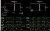
If you plan 50 Hz frequency, then a 4H primary inductance is reasonable. That is the default value when I place a power transformer in the simulator (Falstad's).

However as post #2 states, you can make the frequency faster, allowing you to reduce certain parameters for the transformer.


9:1 step-down ratio converts 230 to 24V. By applying a square wave you get 24V nominal.

It is a sine wave of 24V nominal which rises to a peak of 31V.
 

Status
Not open for further replies.

Similar threads

Part and Inventory Search

Welcome to EDABoard.com

Sponsor

Back
Top