Continue to Site

Welcome to EDAboard.com

Welcome to our site! EDAboard.com is an international Electronics Discussion Forum focused on EDA software, circuits, schematics, books, theory, papers, asic, pld, 8051, DSP, Network, RF, Analog Design, PCB, Service Manuals... and a whole lot more! To participate you need to register. Registration is free. Click here to register now.

Active audio filter doesn't work

Status
Not open for further replies.
Hi,


Mathematically the half between two values is:
U_H = (U1 +U2) / 2.

Here U1 = +5V, U2 = -5V
U_H = (+5V + (-5V)) / 2 = (+5V -5V) / 2 = 0 / 2 = 0

Klaus
 

Yes, at first you had the (+) input on the opamps biased at 0V. But they did not have a negative supply so their outputs would be extremely distorted producing only half of every waveform, if you used opamps that work when the supply is as low as 5V.

Then E-Design corrected your bass boost schematic by adding a negative supply.

Then in post #21 you showed it correctly with a negative supply made from a noisy ICL7660.

Then in post #27 you showed a scribbled schematic showing biasing resistors but it did not show if its supply had a negative supply or not (it didn't) and you wrongly copied it to your circuit that had a negative supply.

Then you said you added the "negative USB supply" only to make it work in software but the software should have showed you that the output did not clip symmetrically because the biasing was way off.
 

So, I've finally got the voltage converter and free time. It works, it has plenty of power, but I have big problems with it.
I've tried both filters separately.

1. There is a loud high frequency noise (like a couple of ringing tones). I do not think it is the 10kHz oscillator, it sounds lower than that.
I tried the 100uF capacitor, but it makes no difference. It does however when I wiggle the ground wire below, sometimes it gets quieter.
I tried both USB and 9V battery as voltage sources.

2. (I hope it is a result of the first problem) The filters don't sound as they should. It sounds like the bass boost and highs roll-off are ''trimmed''.

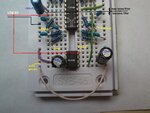
circuit.jpg
 
Last edited:

Your left and right audio inputs have no bias voltage unless your signal source has a low resistance to ground (0V). If the signal source is not a low impedance then the lowpass filters might oscillate.
if you wiggle wires on a solderless breadboard and it makes a difference then the contacts are intermittent. Use soldered parts on a pcb instead.
 

Hi,

Are the electrolytic capacitors suitable for the ICL7660? I'd choose low esr capacitors.

Klaus
 

I tried 100 ohm or 22k resistors between input and ground and it does not help.

Klaus: I don't know, they are Hitano ECR 10uF 100V. I've just found here **broken link removed**
that they have voltage range from 6.3V, is that bad?
 

I tried 100 ohm or 22k resistors between input and ground and it does not help.
If the inputs of the lowpass filters have 100 ohms to ground then your signal source might not be able to drive them. Without a signal then the 100 ohm resistors will cause the inputs to be 0VDC then the outputs of all 4 opamps should also be 0VDC and have no signals. Then did you measure the DC voltage at the outputs of the opamps?
Did the 100 ohm resistors stop the " loud high frequency noise (like a couple of ringing tones)"?
 

You need a negative power supply and USB gives only 0-5v. try simulating your design in proteus or other simulation tool, carefully see the supplies, mostly softwares provide supply to ICs by default.
 

Hi,

Capacitors.
If you want low voltage ripple (low switching noise at the supply rails) you need low ESR capacitors and the ESR needs to be rated at the switching frequency (consider the overtones also).

Your capacitors are specified for mains frequency applications (120Hz), so I'd say they are not suitable for switching in the kHz range.. Adding ceramics capacitors may improve overall performance. Besides the device selection a good PCB layout is essential. Don't expect good results with a breadboard. Especially with this switching frequencies.

Klaus
 

You need a negative power supply and USB gives only 0-5v. try simulating your design in proteus or other simulation tool, carefully see the supplies, mostly softwares provide supply to ICs by default.
Look again. He is using an ICL7660 IC to convert the USB +5V to -5V and since it operates at 10kHz he is using the 10uF filter capacitors that are shown on its datasheet.
 

If the inputs of the lowpass filters have 100 ohms to ground then your signal source might not be able to drive them. Without a signal then the 100 ohm resistors will cause the inputs to be 0VDC then the outputs of all 4 opamps should also be 0VDC and have no signals. Then did you measure the DC voltage at the outputs of the opamps?
Did the 100 ohm resistors stop the " loud high frequency noise (like a couple of ringing tones)"?

No, it did not stop it, it made the sound quieter along with that high frequency noise.
I did not measure, but in case I have a voltmeter.

- - - Updated - - -

Hi,

Capacitors.
If you want low voltage ripple (low switching noise at the supply rails) you need low ESR capacitors and the ESR needs to be rated at the switching frequency (consider the overtones also).

Your capacitors are specified for mains frequency applications (120Hz), so I'd say they are not suitable for switching in the kHz range.. Adding ceramics capacitors may improve overall performance. Besides the device selection a good PCB layout is essential. Don't expect good results with a breadboard. Especially with this switching frequencies.

Klaus

That means adding ceramics parallel to the electrolytics? Which value?


Important thing may be that when there is no input (input jack is unplugged, USB voltage source plugged) there is the noise, and when
I plug in the input jack, it gets louder.
 

No, it did not stop it, it made the sound quieter along with that high frequency noise.
Then maybe the input wiring is not shielded audio cables so it is picking up mains hum and all kinds of other interference including some 10kHz radiated from the ICL7660.

That means adding ceramics parallel to the electrolytics? Which value?
The person who posted about adding ceramic capacitors did not know that the ICL7660 operates at only 10kHz. It would need ceramic capacitors if its frequency is much higher.

Important thing may be that when there is no input (input jack is unplugged, USB voltage source plugged) there is the noise, and when
I plug in the input jack, it gets louder.
yes, that is important.
1) What is the signal source? A cell phone? MP3 player?
2) Do you have shielded audio cable between the signal source and the input of your circuit? The shield connects to the ground at both ends and blocks interference pickup from the air.
3) Try it replacing the USB +5V with a 9V battery to test for "a ground loop". The battery should have a 100uF capacitor across it and the USB must be completely disconnected..
 

Hi,

The person who posted about adding ceramic capacitors did not know that the ICL7660 operates at only 10kHz. It would need ceramic capacitors if its frequency is much higher.

It's not a sine waveform, it is a square wave, with all it's overtones.
In 7660 datasheet they mention, that using low ESR capacitors can reduce the output voltage ripple.

The capacitor is only for mains frequency. 120Hz is far away from 10kHz and the overtones 30kHz, 50kHz...
And it is far away to be a low ESR type.

This is not an opinion, it's the devices specifications.

Besides this the PCB layout has big influence on the ripple.
And thd PSRR of an OPAMP is decreasing with higher frequency. So a 100mV or even a 10mV peak to peak ripple on the power supply is surely visible at the amplifier output.

Klaus
 

Don't know if I earlier made a mistake, but now I tried a 9V battery with my phone and it is vice versa.
When I disconnect the input jack, the noise very slowly gets much louder. It is like twice as much volume I would say.
So both voltage sources (USB, battery) and inputs (PC, phone) are the same. I turned off my computer when using the battery and phone.

The audio cable has not any aluminium wrap, but the USB cable is shielded.
 

My brief comment: It's illusionary to expect no interferences from ICL7660 in a breadboard circuit, it's hard enough to filter the noise on a real PCB.
 

Audio input cables MUST be shielded audio cables, not ordinary wires and not wires with Mickey Mouse do-it-yourself aluminum wrap. The shield in a shielded audio cable blocks pickup of interference from the air.
Earlier you said that the noise is reduced when the wires on the breadboard are wiggled that indicates poor connections.
I wish you could post a recording of the noise. The 10kHz from the ICL7660 would cause a continuous whistle but you said it does not sound as high as 10kHz and you never said it is a continuous whistle.

Now, when you disconnect the input signals the noise very slowly gets much louder, I wonder why it doesn't suddenly increase?
Oh, the lowpass filter is at the input and it MUST have a low impedance input. When you disconnect the signal source then the filter circuit no longer has a low impedance input. Which is why I asked you to try a 100 ohm resistor to ground at each input.
 

I tried to wire the ground pins of the ICL7660 just to the USB ground (so audio ground and USB ground were separated)
and the amp did not work at all, is that okay?

Also I've added a second wire to connect the ground ''columns'' and the wiggle problem is now gone. But, of course, the noise is still there.

I was comparing the noise/whistle with generated tones in software, and I found out that it actually sounds the same as a 9200Hz tone.
So yes, it is more like a whistle.

The noise with a portable device (phone and battery) is the same as with my pc, so I would say it is not a problem of the non-shielded audio cable.
 
Last edited:

Over 2 and a half months ago in my post #15 I said, "Many people say the ICL7660 causes noise if used to power an audio circuit". Instead, I should have said the details that it causes a 10kHz whistle in the sound.
 
  • Like
Reactions: FvM

    FvM

    Points: 2
    Helpful Answer Positive Rating
Over 2 and a half months ago in my post #15 I said, "Many people say the ICL7660 causes noise if used to power an audio circuit". Instead, I should have said the details that it causes a 10kHz whistle in the sound.
You said. Although others claimed that the 7660 noise can be filtered, there are no effective filter means implemented in the circuit. The usual bypass capacitors are insufficient to achieve the signal to noise ratio required for an audio circuit, it does probably work for simple digital designs. The suggested LC (or even RC) filters can help, but surely not with the bread board wiring shown in post #43.

2 and a half months later we have to state that the charge pump idea was bad from the start. A single supply circuit with a suitable 5V OP would have been a much better solution.
 

The MAX1044 voltage converter would have been probably better idea, because I could move the oscillation to higher frequency, I read.

I would try the better capacitors as Klaus said, but I personally doubt the difference would be that big. The whistle is as loud, as the input of the opamp can even get.

So at least my option is now the 9V battery, and adding a bias circuit?
 
Last edited:

Status
Not open for further replies.

Part and Inventory Search

Welcome to EDABoard.com

Sponsor

Back
Top