Continue to Site

Welcome to EDAboard.com

Welcome to our site! EDAboard.com is an international Electronics Discussion Forum focused on EDA software, circuits, schematics, books, theory, papers, asic, pld, 8051, DSP, Network, RF, Analog Design, PCB, Service Manuals... and a whole lot more! To participate you need to register. Registration is free. Click here to register now.

Active audio filter doesn't work

Status
Not open for further replies.
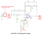
Why? I thought biasing is needed in case of positive supply only?

I read the datasheet but didn't find any information on how to connect it with an amp.
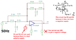
Can it be like this?

icl.png
 

Your bass filter uses an inverting opamp with its (+) input at 0V so its (-) input already has a bias voltage of 0VDC through the negative feedback resistor.
It is the lowpass filter opamp that is non-inverting that needs to have its input biased at 0VDC.

Your ICL7660 is connected correctly but its 10kHz oscillator might be heard in the audio.
 

Hi,

The V+ needs good decoupling capacitors.

Klaus
 

Explaining: To produce the negative voltage the ICL7660 sequences several switches inside it. the switches effectively connect the capacitor across the incoming positive supply so it charges up, then disconnect it, then connect it with the wires reversed across the output. It means each time the switch sequence repeats, it draws a surge of current in the charging phase and the output is a series of pulses. It needs a good quality capacitor across it's input supply to reduce the voltage drop as it pulses input curent and a good quality output capacitor to level off the output voltage. Unfortunately, the switching frequency is only around 10KHz which puts any voltage vaiations in the audible range. It isn't really intended for audio purposes but it will do the job. Try it and see, if you find the 10KHz interference is too high, you can try the block inverter method I suggested earlier, they use a different principle of operation and typically switch > 50KHz so although they may still produce some noise, it will be well outside hearing range.

Brian.
 

Your bass filter uses an inverting opamp with its (+) input at 0V so its (-) input already has a bias voltage of 0VDC through the negative feedback resistor.
It is the lowpass filter opamp that is non-inverting that needs to have its input biased at 0VDC.

I am sorry but I don't get it, is it inverting or non-inverting? I initially thought it is inverting.
I read this page https://ocw.mit.edu/courses/media-a...g-2011/readings/MITMAS_836S11_read02_bias.pdf , searched inverting amp (DC coupled) and figured up that my R1 is 16 ohm , R2=32 ohm and G=2. I didn't get further on, they say ''you can select R3 and R4'' but I thought that will come up as the result. My english is too bad for that..
 
Last edited:

The bass filter is inverting so its (+) input reference voltage should be at half the supply voltage and its input should be a low impedance and can be capacitor coupled.
The lowpass filter that cuts high frequencies is no-inverting and its signal source should be at half its supply voltage.

An opamp cannot use 16 ohm and 32 ohm resistors because they need A LOT of power. Use 16k ohms and 32k ohms instead. Most opamps can drive resistors as low as 2000 ohms but with some voltage loss.
R3 and R4 can be 47k or 100k.
 

Yes, sorry I ment 16k and 32k.

I could not get the full amplitude at 50 Hz when trying to change the R3 and R4 to all kinds of values, but at other frequencies than bass the amplitude is full. Does it mean it will work like this when I lower the input volume? (I will probably change those R3 and R4 to 1M and 220k values)

exa2.pngexa3.png
 

You do not understand biasing.
The (+) input is biased at half the supply voltage so that the output can swing equally the maximum amount up and down.
0V is half of a dual polarity supply and if there is no negative supply then R3 and R4 MUST HAVE THE SAME VALUES.

Your schematic does not show a part number for the opamp so I do not know its spec's. Most opamps have outputs that do not reach the supply voltage, some can go as high as +3.5V and -3.5V when they use a +5V and -5V supply.

Since you have a dual polarity supply then I removed R3 and R4:
 

Attachments

  • active audio filter.png
    active audio filter.png
    39.1 KB · Views: 61

Audioguru:
My opamp is TL074IN, my last picture had this negative USB supply just for it to work in the software.

How should the biasing look like then? You have just posted a schematic which is the same as earlier.
 

How can we discuss your circuit when you showed a schematic with the WRONG power supply?

If you use a single positive power supply then the (+) input on the opamp must be at HALF the power supply voltage so that the output can swing equally the maximum amount up and down.
TI who invented the TL074 quad opamp lists its MINIMUM supply as 7V so you should use 10V or more but I have used one with 9V and it worked.
 

Attachments

  • audio filter.png
    audio filter.png
    11.8 KB · Views: 55

Look at it this way David, you want the output to go up and down in sympathy with the signal you are connecting to the input. It can't magically produce an output voltage which is less than the negative supply or greater than the positive supply. It's those supplies that, through the output stage of the op-amp, become the output voltage.

To be able to produce a signal that can rise and fall around a center voltage of zero, you have to give it both a positive and a negative supply but the input signal itself and the output signal are still referenced to zero.

The alternative method is to shift the output voltage of the op-amp to HALF the supply voltage and then use a single supply. Doing that still allows the voltage to rise and fall but instead of around zero, it is now around the half supply voltage. You set it half way so it has most scope to go up or down from that point. Regardless of how you give it power, the voltage between the +supply pin and -supply pin must be greater than the minimum the manufacturer specifies and also enough to give you your desired output voltage while considering most op-amp output pins can't swing to reach either supply rail. For example, if the amp needs a minimum 10V supply, it can be -5V to +5V centered at 0V or it can be 0V to 10V centered at 5V.

The drawback to using a single supply is the input and the output pins are at half supply so in most circumstances you have to use capacitors to allow the signal to pass through but prevent the half supply voltage being pulled one way or the other by outside components. That's why Audioguru shows the added capacitors in the schematic. Because capacitors are used, there may be some roll-off of gain at low frequencies where their reactance is higher but by choosing suitable values, the effect can be minimal on frequency response.

The biasing on the op-amp in the schematic works like this: in a negative feedback configuration, the amp tries to maintain the same voltage at both input pins. The output DC voltage will fall if the -V input voltage rises and that will in turn reduce the output voltage. It will find equilibrium by adjusting the output voltage so the + and - inputs are at (or very close to) the same voltage. Look at the two 120K resistors, if they are connected between zero (ground) and the positive supply, at their junction there will be half the supply voltage. That is Ohms law! So by holding the + input at half supply, the output will adjust so it is also half supply. The two resistors should be equal value and they should be connected across the op-amp supply so the center is always at Vsupply/2. The 5uF capacitor is there to ensure the half voltage is clean from power line interference but it does unfortunately take time to charge up. While it does, the output of the amplifier will go to higher voltage than half supply but that's just something you have to live with and in most cases will only be noticed as a 'pop' in the audio as the power is turned on.

Brian.
 

Thanks betwix, I think I did understand that earlier.
I just thought that people here kind of remember what we have talked about earlier. Do not get me wrong, I am new to this forum.
I chose to power the op amp with both positive and negative supplies, because the ICL7660 voltage converter will generate negative supply, so I can power it from USB (5 Volts). That will be +5V, and -5V from the ICL7660, total 10 Volts.

Now, even with dual supply it needs biasing, but I don't know how. Earlier I found out that it should be like this, and when I tested it on the virtual osilloscope, I got full amplitude with R3=120k and R4=22k. But Audioguru said that it is wrong. (Please also look at post 27)

exa5.png

- - - Updated - - -

Your bass filter uses an inverting opamp with its (+) input at 0V so its (-) input already has a bias voltage of 0VDC through the negative feedback resistor.
It is the lowpass filter opamp that is non-inverting that needs to have its input biased at 0VDC.

Your ICL7660 is connected correctly but its 10kHz oscillator might be heard in the audio.

I may have not understood it, did you mean my post number 27 was correct?
 

Hi,

I don´t think you have good signal output. In my understanding the DC output should be +12V, but this can´t be.
IN+ of your OPAMP should be GND. At least with the circuit and +5V / -5V supply of post#32.

***
Even with : with R3=120k and R4=22k
I expect a DC output of 3.8V.
With this you may see an output voltage, but with very limited undistorted amplitude.

***
In general I find it confusing, when there is a picture with component values and in the text there are different values.


Klaus
 

I'm getting confused about which schematic is being talked about.

Generally though: if it uses a dual supply, you do NOT need to offset the output with a biasing network. If it uses a single supply you DO need to bias it to (ideal) half supply voltage.

Brian
 

Ok, so that post 27 was correct.
NOPE, it was WRONG.
It shows an opamp with a +5V and -5V supply so its (+) input should be at half the supply voltage that is 0V. But instead you used 120k and 22k resistors to bias its input at the weird voltage of +0.7746...V.
The opamp has its signal source connected to 0V without an input coupling capacitor so the opamp has a DC gain of 48K/12k= 4 times so its output will be biased at +0.7746 x 4= +3.1V and will be almost saturated as high as it can go. The result will be severe clipping distortion.

Maybe you do not understand that 0V is GROUND in that circuit.
 

Hi,

@audioguru.
I agree with you relating to the biasing.

One tiny mistake is with gain calculation:

You say gain is 48k/12k = 4.
--> But from VG1 seen it is "-4".
--> And from V+ seen it is (48k/12k) + 1 = 5. Therfore I expect an output offet voltage of 5 x 0.7746V = 3.87V.

Klaus
 

You're DC gain calculation is correct, Klaus. The output will be so close to the +5V supply that it will have only the negative swing parts of the output signal so it will be EXTREMELY distorted.
 

Audioguru: I don't know then. If you know it, it would be better if you just told me how it should look like instead of to let me trying.

As far as I know, one way to avoid clipping is to reduce input volume, in my case PC. Which is a matter of course, when the filter has +15 dB of bass boost.

You told me that if there is a negative supply, the circuit does not need R3 and R4
,,It shows an opamp with a +5V and -5V supply so its (+) input should be at half the supply voltage that is 0V.''
-I had it at first, but you were telling me that it is wrong and that I do not know that ground is 0V.

exa6.png

The only thing I need to do is to lower the input volume, so there will be no clipping. If it is not true, PLEASE show me how the circuit should look like.
 

Lowering the volume is an option to reduce clipping but also means it's quieter!

If you are using + and - supplies, use the schematic in post #39 as corrected in red. In other words, leave out R3, R4 and C5 and instead, connect the non-inverting amplifier directly to ground. That will make the output pin also be based at 0V with the signal going positive and negative which I think is what you want.

What was meant by
It shows an opamp with a +5V and -5V supply so its (+) input should be at half the supply voltage that is 0V.''
is that half way between +5V and -5V IS 0V.

Brian.
 
Status
Not open for further replies.

Part and Inventory Search

Welcome to EDABoard.com

Sponsor

Back
Top