Continue to Site

Welcome to EDAboard.com

Welcome to our site! EDAboard.com is an international Electronics Discussion Forum focused on EDA software, circuits, schematics, books, theory, papers, asic, pld, 8051, DSP, Network, RF, Analog Design, PCB, Service Manuals... and a whole lot more! To participate you need to register. Registration is free. Click here to register now.

Active audio filter doesn't work

Status
Not open for further replies.

David Kosman

Member level 1
Joined
Aug 30, 2015
Messages
38
Helped
1
Reputation
2
Reaction score
1
Trophy points
8
Location
Czech republic
Activity points
356
sorry for my english.

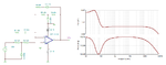
I found these two filters which are exactly what I need.

Should they work built just like that?
I chose this 4x operational amplifier: https://www.ges.cz/sheets/t/tl074_st.pdf
First filter is for bass and the second for highs roll-off.
I'm powering it with 5 Volts from USB.

bas.png 2.png

(the amp is not grounded in the scheme, but I have it grounded)

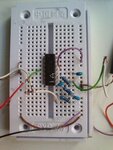
The thing is I've built the circuit for highs, and it seemed that one channel was working and sounded right, but then I suddenly unpluged the jack input and since then it doesn't work. Either the sound is silent, or, when I increase the input volume, it sounds extremely ''craggy/roary''. I also tried the bass circuit and that doesn't work at all.
I don't understand what happened, since the amp should be protected from short-circuit.
I was testing both circuits separately.

I've also tried putting 100 uF capacitor between ground and the USB voltage source, and the zobel network behind the circuit, its the same.

Like I said I think it was working, but then I unplugged the input and since then it doesn't work.
thanks for responses
 

The circuits both have ground referenced inputs, that means you must supply the op-amps with both negative and positive supply voltages. In other words a positive above ground and a negative below ground.

You can adapt the circuit to work from a single supply but those op-amps will not work from as supply as low as the 5V from the USB socket anyway.

Brian.
 

Quote: "(the amp is not grounded in the scheme, but I have it grounded)"
Please post a schematic showing exactly what you have. If you have a negative supply then show it. If something is grounded then show where.
The opamps have nothing to bias their inputs when the input signal is removed.
 

DSC_0916 (1).JPG

Here it is, sorry for the chaos. I have also tried leaving the USB ground only for the negative amp supply, it is the same.
 

Attachments

  • DSC_0916 (1).JPG
    DSC_0916 (1).JPG
    1.3 MB · Views: 121

As mentioned, if you connect the supplies correctly you will get some results.

I think you can design and simulate a circuit with the TI web application and when you are satisfied you can download that circuit as a Tina-TI file to your computer.
 

Attachments

  • LP.png
    LP.png
    26.1 KB · Views: 146
Ohh, now I get it. Thats why I didn't have it in my schematic, because I just grounded the negative amp supply, that didn't work in the software.

But now I really don't know what to do. Does it mean I need TWO voltage supplies? The whole op-amp should be able to be powered with 5 volts, thats USB.

Do I also need a battery or something? I am really confused.

Edit: Could I use another USB port as the negative supply?
 
Last edited:

Texas instruments invented the TL074 quad low noise audio opamp. They say its minimum supply is 7V because its inputs do not work properly if they are within 4V from its negative supply. Like any opamp, it can use a single positive supply if its input is biased at about half the supply voltage that is 0V (ground) if the supply is positive and negative.

There are opamps available that work from a single +5V supply if their input is biased at about +2.5V. But its maximum output swing might be too low for your audio circuit.

You cannot use two USB ports because both have the same 0V and produce only positive voltages, no negative voltage.
 

... but you are understanding correctly, you need TWO supplies, one positive with respect to ground and one negative with respect to ground. The op-amp can not accept input voltages below zero or produce output voltages below zero unless you give it a negative supply. As Audioguru points out, that particular type of op-amp is incapable of making it's output pin go close to either supply line voltage so you would need significantly more than 5V to give it room to produce usable output levels.

There are options open to you but they will cost a little more:

1. generate a negative supply line from the existing positive one. You can buy small modules to do that or you could consider the venerable 7660A voltage converter.
2. use low voltage op-amps and shift your ground to a fixed +2.5V (half supply voltage) so the amp thinks it has a +2.5V and -2.5V supply.

Brian.
 

Hi,

There are rail to rail Opamps working on a single 5V supply...But you need to change the circuit and add bias voltage..

Klaus
 

Ok, I need to ask:

- if the lowest voltage for op-amp is 5V, does it mean 2,5V for positive and 2,5V for negative?
- What would be the best solution for my circuits? Because the difference in frequencies will be up to like 25 db, would the output swing be too low for it? (I have a headphone amplifier in some case)
- my opamp is then usuable with USB? I don't know where did I find that the lowest for it is 5 volts.
- do you have some example of that module for generating the negative supply?
 

Hi,

One important question is: Do you need DC performance (input to output)?
If you can live with a lower cutoff frequency of - lets say - 10 Hz, then this makes all easier.. Then we use capacitors for coupling...


If you need DC performance, then use - as already suggested - a (TC,TL,ICL...) 7660 circuit to generate negative voltage.
Supply the OPAMP with +5v and -5V.

Klaus
 

Google for NME0505. (zero 5 zero 5)

It has it takes 5V in at one end and produces an isolated 5V out at the other. Because it is isolated, you can connect the '+' at the output side to your ground and the '-' at the output side will then be a -5V rail.

There are many op-amps that work down to 5V supply but you need significant changes to the schematic to lift the signal ground to 2.5V to use them. I would be inclined to try the NME0505 solution with your existing design for simplicity.

Brian.
 

- if the lowest voltage for op-amp is 5V, does it mean 2,5V for positive and 2,5V for negative?
Yes, but then it barely works because either its inputs or its output will have the minimum amount of voltage swing.

- What would be the best solution for my circuits? Because the difference in frequencies will be up to like 25 db, would the output swing be too low for it? (I have a headphone amplifier in some case)
25dB is a change in voltage of about 18 times which is not much change since we can hear a change of at least 60dB (1000 times). We do not know how much signal the headphones amp needs to be loud enough.

- my opamp is then usuable with USB? I don't know where did I find that the lowest for it is 5 volts.
No, its inventor and manufacturer says its MINIMUM power supply is 7V or plus and minus 3.5V when it BARELY works.

- do you have some example of that module for generating the negative supply?
It is on its datasheet (ICL7660) but many people say it causes noise if used to power an audio circuit.
 

Hi,

(ICL7660) but many people say it causes noise if used to power an audio circuit.

I used the ICL7660 many times... For precision measurement I connect an LC filter at the output.
A 16 bit ADC in the audio range is stable down to the LSB.

--> with a small filter and a good layout I don't expect problems.

****
But on my PC a headphone amplifier and a USB soundcard, both are influenced by power supply fluctuations..One can hear every processing activity...

Klaus
 

Unfortunately, NME0505 is not available anywhere in my country.
I will buy the ICL7660A then.

I think I will want to power it with USB, so is LM324N opamp a good idea? By the way, what does mean ''the common
mode input range includes the negative supply, thereby eliminating the necessity for external biasing components in many applications
'', I will need the ICL7660A anyway?

For the ICL7660A - the positive voltage source will go to opamp, and to the ICL7660A in parallel, just like that? And sorry if I am stupid, but the ICL7660A will make ANOTHER 5 volts (not split it in halves)?
 

An LM324 quad or LM358 dual is THE WORST opamp for audio because:
1) It is noisy (hiss).
2) It has crossover distortion.
3) Its has trouble producing high levels above only 2kHz (poor slew rate).

Your schematics show opamps with nothing biasing the inputs so the opamps will not work.
If the input signal source has a DC voltage of 0V then the opamps will work if the supply is plus and minus but the opamps will rectify the audio if an opamp is used that has a common mode input range including the negative supply and a single positive power supply is used, OR you bias the opamps properly at half the single positive supply voltage then ANY opamp will work if the supply voltage is enough.

The ICL7660 has a datasheet that you should read. It says when its load current is low then with a +5V input it can produce a -5V output. Then your opamps will have a TOTAL voltage of 10V. The ICL7660 produces 10kHz of ripple that might be heard.
 

I have just realized that I don't need a new opamp when the total voltage will be 10 volts, thank you.
I will find some information, make a schematic and post it here to ask whether it is going to work.
 

A TL074 opamp will not have much signal output when the total supply is only 10V but it might be enough for you. With the plus and minus supply it will need resistors to bias its inputs at 0V.
 

Status
Not open for further replies.

Part and Inventory Search

Welcome to EDABoard.com

Sponsor

Back
Top