Continue to Site

Welcome to EDAboard.com

Welcome to our site! EDAboard.com is an international Electronics Discussion Forum focused on EDA software, circuits, schematics, books, theory, papers, asic, pld, 8051, DSP, Network, RF, Analog Design, PCB, Service Manuals... and a whole lot more! To participate you need to register. Registration is free. Click here to register now.

variation in reading voltage by atmega8 adc

Status
Not open for further replies.

mahdiiust

Junior Member level 1
Joined
Jan 22, 2013
Messages
16
Helped
0
Reputation
0
Reaction score
0
Trophy points
1,281
Activity points
1,430
Hi
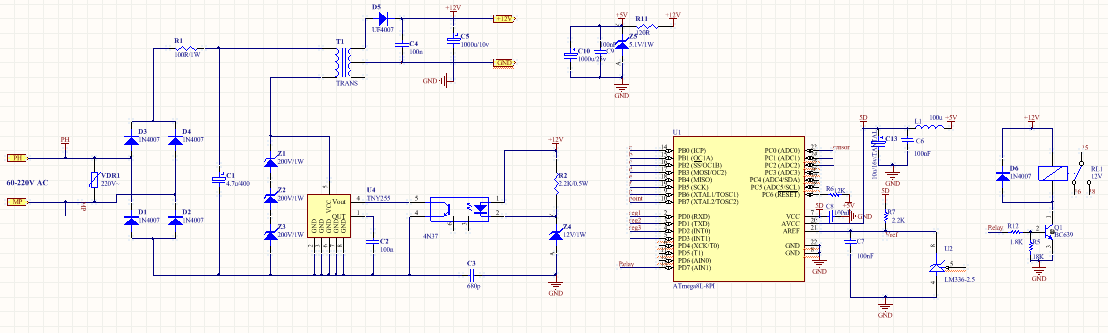
I designed a circuit with atmega8 for measuring a voltage and then if over voltage is occured a 12V relay will be on. but when the relay is on, the measured voltage reduced. I use LM326-2.5 as reference voltage on Aref pin.
what is the problem? Is it related to my PCB design? the schematic is below.

Thanks.
 

The schematic doesn't appear in the post. If the relay is on the same line as the measured voltage then maybe its voltage drop is reflected in the adc measurement.
 
Hi,

There is no ATMEGA128 in the schematic.

***
To your problem:
Maybe your problem is caused by "ground bounce", caused by the changed ground current of the microcontroller when the relay is switched.
Or you have a pcb layout problem...
Or a power supply problem...

Try to include a hysteresis in your voltage comparator code.

Klaus
 
thanks!
yes I did not draw Atmega8 because I think the problem is related to power supply.
So should I modify my PCB and try again?
what is hysteresis?
 

Hi,

we can only guess, as long as you don´t provide the related schematic.

So should I modify my PCB and try again?
PCB layout has also a big influence on ADC reading precision.
Maybe power supply.

My recommendation:
Find out where the error comes from, then change this detail.

So should I modify my PCB and try again?
If you have too much time, you are free to use the trial-and-error-method.

****
give informative data. You gave:
* ATMEGA8: the controller itself won´t craete this problem
* 12V relay. Relay voltage is not important. The relay itself will not cause your problem
* the same is with your LM326-2.5 reference.
--> no useful information.

****
Hysteresis:
--> wikipedia ia always a good source for informations: https://en.wikipedia.org/wiki/Hysteresis
In short: It is not a good idea to switch ON/OFF any device at a fixed threshold.
Instead you could switch on your relay at voltages above 12.1V and switch it off at voltages below 11.9V.
The difference voltage between ON and OFF = 12.1V -11.9V = 0.2V is called hysteresis.

Klaus
 

Thanks
In fact I design a circuit for measuring the temperature and if the temperature is hotter or colder than a defined point, the relay will be on. but after the relay work the temperature changes (increases). to determine the source of problem I measure some voltages. The sensor and LM324-2.5 voltages do not change but the 5.1V zener and 12V zener decrease to 4.88 and 11.8 volt.
Even I connect the 5.1V zener and 12 volt zener directly to an external power supply with 5.1V and 12V fixed voltages. But the problem is still here!!


Hi,

could you please give a more detailed schematic picture. I can not read the values of the resistors.
What is connected to portB and portD?
I can´t find the temperature sensor and the filter to the ADC.

In the ATMEGA8 datasheet there is an example circuit for AVCC. It should be decoupled from VCC (L between VCC and AVCC). Your circuit is not according datasheet in this.
****
It is quite typical that (supply) voltages change when the load changes. But how much can be tolerated?
An LM7805 probably gives a more stable output than the zener. Also it usually has less power dissipation. But i doubt this solves your problem.

****
I assume there are several problems.
1) measurement of analog signal. Here I assume the problem is in the PCB layout. Did you use a GND plane?

2) a software problem on how to switch the relay.
Imagine your threshold temperature is at 100°C. So at 100.001°C the relay should be ON. And at 99.999°C the relay should be OFF. But what if it is exactely 100.000°C?
Now you may say it is impossible to decide down to 0.001°C with your circuit. True. But where is the limit?
Maybe one LSB represents 0.25°C.
But there is noise. Noise from the sensor, from the wiring, influence from the environment (EMV), power supply, and the ADC itself.
It is impossible to get a stable digital value from an ADC when it is connected to external circuitry. It may be stable for several readings, but as soon as the input voltage moves a little it comes to a point where the ADC has to decide between two digital values (one LSB apart).
Exactely there you have the problem with the infinitesimal voltage values, down to nanovolts.... and these nanovolts decide wheter your relayis ON or OFF... Impossible.

***

Solution:
* Let us check your PCB layout. Maybe we find an issue. AND you need to install one of the folowing alternatives:
* Either use a timed relay solution. Maybe if the relay switches to ON, it stays ON at least for 5 seconds....before it may switch to OFF, then it statys OFF for at least 5s again. (for sure you can adjust the time)
* Or you include a (temperature, voltage) hysteresis. Maybe 1°C is enough hysteresis for clean switching....

Klaus
 
Status
Not open for further replies.

Similar threads

Part and Inventory Search

Welcome to EDABoard.com

Sponsor

Back
Top