Continue to Site
Follow along with the video below to see how to install our site as a web app on your home screen.
Note: This feature may not be available in some browsers.
Does the overcurrent occur at a certain point in each mains waveform? When mains voltage amplitude is near zero (twice per cycle), is your amplitude high? Then that means your waveform is pouring current at the wrong point in the mains waveform. It could be a power factor issue.
so an unexpected voltage spike across my zero point is possibly the reason of the overcurrent? and the solution should be to produced a perfect sine wave in my output?
If you have a transformerless inverter with PWM control, then the current must be controlled to match the (filtered ) voltage with no phase error, such that the net power dissipation in your inverter is never exceeded. Do you have this control?
Do you have ;
- Suitable margins for component specs. with a design spec?
- thermal sensing,
- current sensing?
- over voltage protection?
- surge filtering?
- Soft start protection?

Nice chat, unfortunately without substantial information about the inverter circuit and control method.
- - - Updated - - -
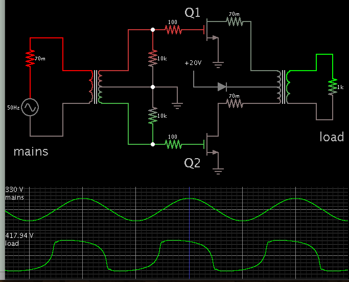
As a first step, basic information about the topology is needed. If it's like below, overcurrent may be easily produced by SCR trigger or commutation problems.
View attachment 122904
Where do you observe overcurrent? In the flyback output or at the grid interface?
And for my test I added an Isolation transformer in between my AC line and my inverter. I tried again another test and I take the isolation transformer out, its kinda risky but there is no over current that happens.