Continue to Site

Welcome to EDAboard.com

Welcome to our site! EDAboard.com is an international Electronics Discussion Forum focused on EDA software, circuits, schematics, books, theory, papers, asic, pld, 8051, DSP, Network, RF, Analog Design, PCB, Service Manuals... and a whole lot more! To participate you need to register. Registration is free. Click here to register now.

2 inch 7segment display.

Status
Not open for further replies.

tapu

Full Member level 4
Joined
Sep 15, 2014
Messages
234
Helped
1
Reputation
2
Reaction score
1
Trophy points
1,298
Location
india
Activity points
3,041
Dear all,
I am using 2 inch seven segment display. For my project.but data is not showing in display.here I connect port of 8051to display directly (According to program)..is ic 2803 required for current sink??
 

is ic 2803 required for current sink??

Yes...When you configured your controller pins as outputs (logic zero (0)), single port pins can receive a current of 10mA. If all 8 bits of a port are active, a total current must be limited to 15mA (port P0: 26mA). If all ports (32 bits) are active, total maximum current must be limited to 71mA. When these pins are configured as inputs (logic 1), built-in pull-up resistors provide very weak current, but strong enough to activate up to 4 TTL inputs of LS series.
But your display Typical 1500 μcd at 5 mA is best in class performance for applications with very limited power supply. The maximum peak current of 70 mA is allowed.

So you would need a current sinking or current controlling.

1. You can use series rasister at 8051 output
2. You can use a single rasister at 7 seg common pin
3. You can use a driver IC like 5411.
4. You can use a transister array IC like ULN2003A.
 

Thank you for reply.how much voltage required for 2 inch seven segment display.?Because I could'nt check it by 5v adaptor.I have checked by 9v battery.
 

what are you using for current sinking?

- - - Updated - - -

Because LED work with current ratting
 

Hi,

how much voltage required for 2 inch seven segment display.?
How can we know?

Only you know what type of display you use.
There are different types with different current and voltage rating, different connections, different brightness, different colors.

Klaus
 

I saw a datasheet of 2" 7seg and i found it's forward current is 20ma-30ma according diffrent colors. No matter how mutch voltage you are using. LED want 20ma current.

Voltage = 9 or 5
R = V/I
R = 9v/0.020a or 5v/0.020a
R = 450E or 250E

You would use 450E rasister with 9V and 250E with 5V.
 

Hi,

No matter how mutch voltage you are using

Nonsense.
For sure there is the voltage rating in the datasheet. It is essential.
Most of the 2" displays need more than 5V.

If you try to connect those to 5V (with or without a 250 Ohms resistor) nothing will happen.
Even the calculation of the current limiting resistor is wrong. It should be R_V = (V_supply - V_LED) / I_LED

Look into the datasheet of your display to see the display ratings.

Klaus
 

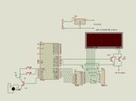
SCH.JPG

Here 12v supply is given to seven segment display which is 2 inch red colour.
Data does not show in display.I want to know a problom.please reply.
 

Hi,

The current limiting resistors should be in series with the signal lines.
The anode driver transistors are connected wrongly. They won't supply 12V to the anodes.
Consider to use fast high side drivers instead.

Reset is not connected,
All Vcc and and 12V capacitors (bulk and high speed) capacitors are missing.
D1 has no current limiting resistor.
The emitter flower for D1 has high voltage drop.

I recommend to look at other schematics and copy them.

A display without datasheet ... no one can be sure it works..

Klaus
 

Dear klaous, the circuit runs in Proteus simulation.but not in actual hardware.
 

Hi,

No wonder with all the issues.

Here you can see that a simulation is only as good as the data given into it.

Klaus
 

Due to size of 7 seg LED 2" and up, they put several LED's in series running at 20mA due to heat rise. Some are 10, others 40mA0
Since deep RED GaAs LEDs are 1.85V then 4 LEDs per segment are 7.4V per segment, this varies between colour and part numbers
Most are Common Anode (+), some are Common Cathode(-)

YOu choose the current limiting resistor from OHm's Law but must know digit driver is much lower resistance that all segments ON from Vo/Io drop or rise in voltage across switch.

Each small LED is around 16 Ohms so 4 in series is around 64 Ohms per segment is around the Vf of 7.4V which will acount for VI variations of LED.
If they are multiplexed then Peak current must not exceed 5x ( ie 5 digits) to obtain average current of 20mA then driver must be even 5x lower RdsOn or Rce. Remember that BJT's need 10% base current to drive collector into saturation.

LED examples
https://www.digikey.com/product-sea...t=0&page=1&quantity=0&ptm=0&fid=0&pageSize=25
 

Dear All,
Thank you for taking time for me.One thing I noted in this problom that the output of a regulator shows 4.10v.which is less for controller & circuit.But how to get proper 5v output from 12v adaptor.the supply circuit I had buit is as follow.SCH1.JPG
 

Hi,

If the output voltage is not 5.0V +/-5%, then
* the circuit is not as shown
* the input voltage is too low
* the output current is too high
* a part is defective (including DMM)
* ...

Klaus
 

Hello tapu

Each simulator has its things to improve; ISIS's Proteus too.
Mysteriously its IC ULN2803 require pull-up resistors to operate (RN2).
Apparently the resistors connected in series with the Display segments, the transistors and the 12V power supply does not serve him as such. (Pull-Up).

Remove the chip resistors RN2 and see that design do not work. (Attached)

Let us see now the display.
You need to know the electrical characteristics of your display and the other associated components to the circuit.

Assuming that your display has the following electrical characteristics:
VF = 3.0 Volts
IF = 10 mAmp.
If only you had the display and the 12V adapter, it would be easy to calculate the value of current limiting resistors for the segments of the display.
It would be as follows: (VCC - VF) / IF = Rx.

But you have in your design a transistor (BC547) which hinders our calculations a little.
We need to know the electrical characteristics of this transistor.

In practical life is first look at what is needed, and Then look for a device that meets our requirements.
Just think, when the display lights up number 1, there are only two lit segments. . . So by the emitter-collector junction of transistor circulate a current of 20mAmp.
And when it turns the number 8, for the same joint will circulate a current of 80 mAmp. The worst case.

How much IC current supports this transistor ??
Data Sheets (attached) tell us that IC = 100 Amp. Continuous.
Mmm. It can be used to this design.
Now, how much current we have to apply to the base of transistor to give us 80 mAmp IC ??.
Again we see the data sheets and find that this transistor has a typical gain of 120 hfe. So: 80/120 = 8 mAmp Ib.
Note: This hfe is given when the IC = 100 mAmp and VCE = 5 Volts.
In such a way that the value of the limiting resistors for the segments of the display would be calculated as follows:
(Vcc - (VCE + VF)) / IF = Rx.

How much voltage, at the output, can provide your microprocessor ??.
We need to analyze the data sheets of a microprocessor.
We need to know the value of this voltage to calculate the value of the base resistor RB.
Let assuming, for practical purposes, giving us 4.5 V.
RB will then be calculated: RB = 4.5 / 0.008 = 1.125 K Ohms.

You can also make these calculations working with the transistor in saturation mode. I think it's better.
In which case you only have to replace, in the formula, the value of VCE parameter. by VCE (sat)

Because I have not the program for the microprocessor, regardless of 8051, mentioned in your original message or 89C52, seen in the image that you enclose in your post #8, I made a design with other devices.
Note that the ULN2803 inverts the logic levels. Furthermore PIN 10 is connected to VCC only when using inductive loads.

I hope that helps You with all this talk.
 

Attachments

  • The Chematic.PDF
    631.5 KB · Views: 75
  • The Chematic.zip
    20.6 KB · Views: 55
  • BC547B Motorola .pdf
    214.8 KB · Views: 56

Hi,

So: 80/120 = 8 mAmp Ib.
Isn't it 0.667mA?

This is the limit.
I recommend to use 2...8mA Ib to be in saturated area.

Klaus
 

Yes KlausST I pushed the wrong key.
And Yes Also To Your recommendation

We need to analyze whether the transistor works for the frequency to be exposed.
But we do not know
 

Dear all,
Above problom have solved.but I want to use tip122 instead of bc547.for better performance.which value of base resistor required or how to calculate it?(becouse i did not use resistor in above circuit then probably pins has damaged)
 

Hello tapu

You need to know the electric characteristics of your 2 inch 7 segment display in order to calculate the Rb for those TIP122 transistors.

Do you know these characteristics??
 

Status
Not open for further replies.

Similar threads

Part and Inventory Search

Welcome to EDABoard.com

Sponsor

Back
Top