Continue to Site

Welcome to EDAboard.com

Welcome to our site! EDAboard.com is an international Electronics Discussion Forum focused on EDA software, circuits, schematics, books, theory, papers, asic, pld, 8051, DSP, Network, RF, Analog Design, PCB, Service Manuals... and a whole lot more! To participate you need to register. Registration is free. Click here to register now.

hi frequency inverter with SG3525

Status
Not open for further replies.

sawani

Newbie level 5
Joined
Dec 6, 2009
Messages
9
Helped
0
Reputation
0
Reaction score
0
Trophy points
1,281
Activity points
1,367
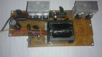
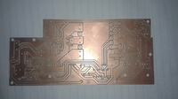
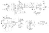
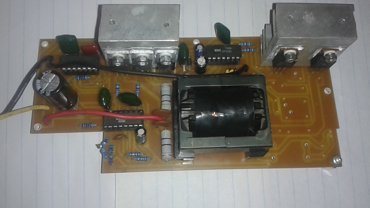
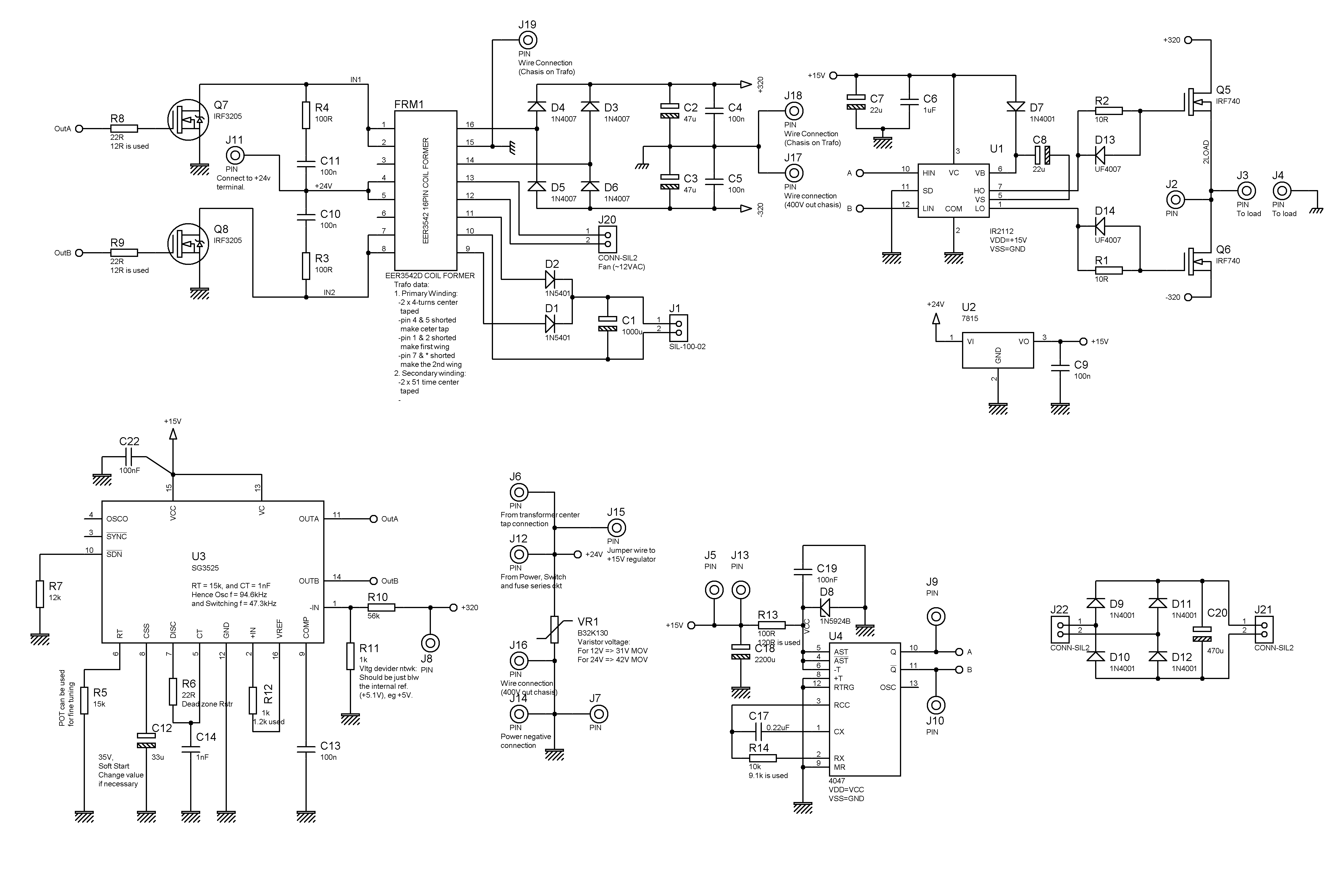
Hi friends. Hope someone can help out. I am trying to build a high frequency inverter using sg3525. I did my own transformer. The core is EER3542D, with 4turns x2 for the primary and 52 turns x2 for the secondary. The problem is the Mosfets (that drive the primary) keep on burning. I am less experienced with the high frequency inverters and surely now I have exhausted my knowledge on them to find the problem. I am posting the schematic here and the pcb if someone can see what I am doing wrong. For whatever you thing and post I will appreciate. Thank you all in advance.
Notes:
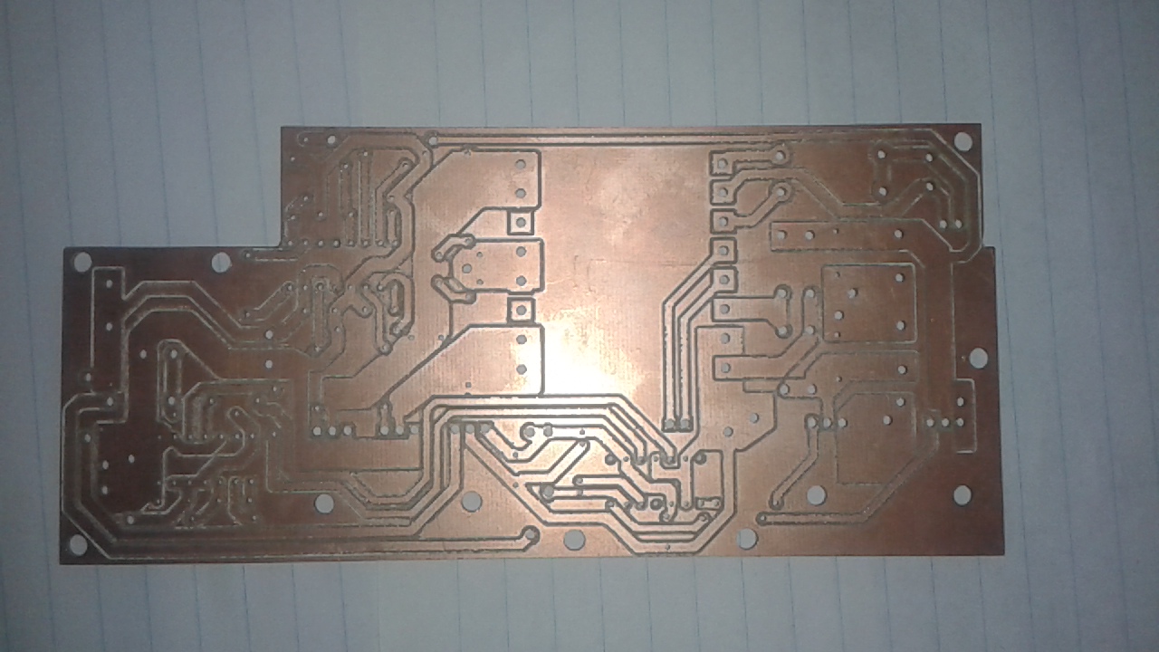
1. On the picture the output rectifiers and filter capacitors are not soldered yet
 

In4007 can handle only 1Amp and it can not work on HF.
 

In4007 can handle only 1Amp and it can not work on HF.

Thank you ALERTLINKS. Sure, they do not work on HF. I forgot to change that on the schematic. I actually use FRI54. 1 amp is not a problem. It is enough for the purpose. The problem is the mosfets on the primary side (i.e. Q7 and Q8) die just within a minute after connecting the circuit to the power. Can you figure out where I make a mistake? Thank you again :).
 

what kind of load are you using ? I just built an smps and I attached too big of a load for the transistors I were using at first I didint calculate the amps the transistors would have to carry on that load then they blew up and I calculated the load and it turned out the load was too big.
 

A possible problem could be that the voltage overshoot caused by the transformer leakage inductance is exceeding Vds,max of 55V. An oscilloscope measurement can tell. The weak snubber is probably not sufficient to absorb the voltage spikes, a RCD snubber would be better suited.
 
  • Like
Reactions: sawani

    sawani

    Points: 2
    Helpful Answer Positive Rating
what kind of load are you using ? I just built an smps and I attached too big of a load for the transistors I were using at first I didint calculate the amps the transistors would have to carry on that load then they blew up and I calculated the load and it turned out the load was too big.

Thank you Salvador12 for your replay. The load is only five mobile phone chargers. But the transistors dies when I test the circuit. I haven't yet put any load. as you can see on the picture even the output circuit that would curry the load isn't yet in place. Just the SG3525 with the MOSFETS driving the trafo, the the FETS dies within a minute. FvM is talking about voltage overshoot from transformer leakage on the comment below yours. I think I got to look into it too. Thank you again for tanking your time and look at my schematic, Salvador12.
 

A possible problem could be that the voltage overshoot caused by the transformer leakage inductance is exceeding Vds,max of 55V. An oscilloscope measurement can tell. The weak snubber is probably not sufficient to absorb the voltage spikes, a RCD snubber would be better suited.

Hi, FvM. Thank you for your replay. I started studying the overshooting problem since I got your reply and it seems that I need to do some calculations of which some of the inputs (like the inductance of the primary coil) will be hard to get. Also I do not have oscilloscope at hand, that make the matter worse. Now, I want to do trial and error with the snubber circuit, but since I do not yet know exactly how the circuit work, I do not know what are the safe values of the components to start with. And also which should be fixed while I vary the others. Also in order to start from the save side going to the dangerous side with the one which I will be varying, should I start from low value to high value or from high value to low value. I will appreciate your help on this, or any different suggestion. Thank you very much in advance
 

Check your winding turns of your hf transformer
 

your RHS ir2112 does not look connected up properly...I cannot see a connection to the bridge node. (the source of the upper fet)
 

As this is a push pull forward converter, there will need to be a pair of chokes fitted between the + and - outputs of the main bridge rectifier and the filter capacitors. The auxiliary supply also needs a choke.

That is, C1, C2, and C3 should each be fed by a choke.

Without these chokes there is nothing to limit the turn on current of the switching mosfets. These chokes are an extremely important part for the correct functioning of any forward converter, and cannot be omitted.
 

Status
Not open for further replies.

Part and Inventory Search

Welcome to EDABoard.com

Sponsor

Back
Top