Continue to Site

Welcome to EDAboard.com

Welcome to our site! EDAboard.com is an international Electronics Discussion Forum focused on EDA software, circuits, schematics, books, theory, papers, asic, pld, 8051, DSP, Network, RF, Analog Design, PCB, Service Manuals... and a whole lot more! To participate you need to register. Registration is free. Click here to register now.

Help, FCC/CE certification issue of CMOS RF transceiver

Status
Not open for further replies.

buckaroo

Member level 3
Joined
Apr 23, 2007
Messages
60
Helped
6
Reputation
12
Reaction score
4
Trophy points
1,288
Location
Beijing
Activity points
1,626
Dear All,

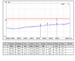
I have a 2.4GHz CMOS RF transceiver for FCC/CE certification, the FCC result is OK, but the CE result is marginally passed, the CE certification result showed that the 4.8GHz (it is on chip VCO frequency=2*fLO) leakage power is about -50dBm, while the CE requirement is <-47dBm, so we do not have enough margin...
the leakage power@Antenna is <-60dBm, which means the reverse isolation of RX path is OK, then, where does the 4.8GHz leakge power come from(is it from the radiation of on chip VCO?)? how can we improve it? I am confused, help me, thanks very much!

BRs
Buckaroo
 

Attachments

  • CE.png
    CE.png
    65.6 KB · Views: 104

Yes most likely from top of chip.
Does it have a lid?
How is ground plane designed?
Are IO wires filtered with beads?


Dear SunnySkyguy,

Thanks for your reply.
Yes, it is a SoC chip with RF baseband and MCU.
Because it is a kind of consumer electronic, the cost is important, and hence we don't have lid or beads.
The whole chip ground plane is connected together (ground mesh) except PA ground(QFN package, all ground pins downbonded), however the PCB ground is NOT connected together by a whole metal layer due to the limitation of 2 layer PCB.
I am confused that the 4.8GHz (=fVCO=2*fLO) leakage power@antenna is about -70dBm, but the CE certification result is as high as -49dBm, I guess it is most likely from radiation of on chip VCO inductor tank. I am a RFIC designer without FCC/CE certification experience before, it is tricky
Thanks

BRs
Buckaroo
 
Last edited:

We used to make our own shields from sheet brass, tin plated , etched at a PCB shop with fold marks and solder tabs. But you can also buy from Tech-etch (I think) or their distributor in china. (mindar). Some had lids.
 
We used to make our own shields from sheet brass, tin plated , etched at a PCB shop with fold marks and solder tabs. But you can also buy from Tech-etch (I think) or their distributor in china. (mindar). Some had lids.

Dear SunnySkyguy,

Thanks,
Finally, it was found that the harmonic is due to the VCO test buffer leakage.

BRs
Buckaroo
 

Status
Not open for further replies.

Part and Inventory Search

Welcome to EDABoard.com

Sponsor

Back
Top