Continue to Site

Welcome to EDAboard.com

Welcome to our site! EDAboard.com is an international Electronics Discussion Forum focused on EDA software, circuits, schematics, books, theory, papers, asic, pld, 8051, DSP, Network, RF, Analog Design, PCB, Service Manuals... and a whole lot more! To participate you need to register. Registration is free. Click here to register now.

[SOLVED] Fan Speed Controller Circuit - 78L05 and 555

Status
Not open for further replies.

IagoPereira

Newbie level 5
Joined
Oct 10, 2015
Messages
8
Helped
0
Reputation
0
Reaction score
0
Trophy points
1
Activity points
47
Hello there!
Before anything, this is my first post, I'm a portuguese Engineering student and I'm trying to build this little project of mine... A cooling table for my brothers laptop!
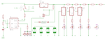
My target is to make a small regulator, so that when I speed up the fans the LED's 4,5,6,7 and 8 turn on, one by one as I speed up the fans, and when I turn the turbo switch on the 555IC makes those LED1,2and 3 flash! The turbo and flashing LED is working, but I'm not sure about the rest, in attachement I leave the schematic, please tell if this circuit is going to work, and if not, why and please help me fix it!

Thanks :):)
 

Attachments

  • Design_1.png
    Design_1.png
    10.4 KB · Views: 130

First off all remove the ground from S1, it will short out your supply. The arrangement for your three 7805s is exactly wrong! because as you vary the voltage across the motor the LEDs get a steady voltage. A much better way of doing it is to use a lm3914 IC. It takes a variable voltage input and drives the leds.
Frank
 
IC2 should be a variable regulator like an LM338 rather than a 78L05z.
 

Thanks, I will make a new circuit using the LM3914 and post it here for you to see, can it be?

- - - Updated - - -

So, now I made this, I dont know why, but it was not suposed to a 7805 but an LM317, whatever though... So, now, what do I do for the input?Design_2.png
 

Your LM317 is missing the important input and output capacitors shown in its datasheet. The resistors you selected will set its output from 1.2V (too low) to 27.2V (impossible).
The fans need a high current to start running but a voltage regulator cannot do it, also the voltage regulator is linear that wastes a lot of power making heat.

Today, the speed of electric motors is made with Pulse-Width-Modulation that feeds the motor with high current pulses for good starting and the spacing times between the pulses controls the speed. Google shows some good PWM motor speed control circuits that use a 555 and an N-channel Mosfet.

Your LM3914 has its SIG IN pin5 not connected to the voltage that feeds the motors and you do not have a reference voltage on R HI pin6 so it will not work. You have 240 ohms for R7 which sets the reference current too high at 5.3mA then the current in each LED will try to be 44mA which is WAY TOO HIGH. The LM3914 does not need the 12V regulator.
 
You are dividing down the input signal voltage to the LM3914 but then its input is close to its comparators input offset voltages. It would be better to increase the reference voltage by connecting two series resistors from pin 7 to ground and connecting pin 8 to the junction of the resistors, similar to the LM317. Then the resistor ladder feeding the comparators in the LM3914 have much higher input voltages. The two resistors control the LED current and brightness. Then maybe the entire output voltage of the LM317 can feed SIN IN on the LM3914.
Again, your new LM317 has a minimum output voltage of 1.2V which is too low and since R LO pin4 on the LM3914 is at 0V then the bottom few LEDs will light when the motors are not running at the very low voltages.
Pin 4 needs a resistor to ground to increase the required minimum input voltage that will light the lower LEDs. But you do not know the voltage when the motors will start running since you are not using Pulse Width Modulation.

Can you please show me how you would do this circuit with the changes you talked about and the PWM?
 

Now i have this, but I don't know where to connect R8 nor the 'Turbo'.... Design_4 PWM.png
 

The PWM will control the speed of the fans very well. But the 555s and LM3914 do not need the 12V regulator so it can be removed.
The input to the LM3914 is PWM pulses so it will show all LEDs lighted almost at every speed setting. The brightness of a few LEDs will show the speed. If you want the dot of a single LED to show the speed (except most LEDs to show most of the bar at high speed settings) then add a capacitor parallel with R9 to smooth the pulses into a DC voltage.

With a 15V supply and 2V red LEDs then each output transistor in the LM3914 will have 13V across it when it is turned on, and a current of 11mA so the IC dissipates 13V x 11mA x 10= 1430mW when all 10 LEDs are lighted which will melt the LM3914 because its maximum is 1365mW. So add a 56 ohms/2W resistor between the +15 supply and the anodes of the LEDs to share the heat. Add a 10uF capacitor to ground at the anodes of the LEDs.
 

Status
Not open for further replies.

Similar threads

Part and Inventory Search

Welcome to EDABoard.com

Sponsor

Back
Top