Continue to Site

Welcome to EDAboard.com

Welcome to our site! EDAboard.com is an international Electronics Discussion Forum focused on EDA software, circuits, schematics, books, theory, papers, asic, pld, 8051, DSP, Network, RF, Analog Design, PCB, Service Manuals... and a whole lot more! To participate you need to register. Registration is free. Click here to register now.

Buck converter does not step up current but steps down voltage

Status
Not open for further replies.

mugheesnawaz

Member level 1
Joined
May 1, 2013
Messages
39
Helped
1
Reputation
2
Reaction score
1
Trophy points
1,288
Activity points
1,605
Hi all.
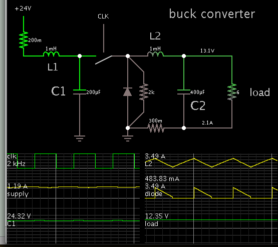
i am designing buck converter to step down 24 volts to 12 volts to charge a battery.
so far i am successful in stepping down the voltage but the main issue which i am facing is that input current is higher than output current which should be the other way around.
i am using ir 2112 as gate driver.kindly tell me where i am wrong because buck converter should step down voltage and step up current.


cct.png

View attachment Buck with ir2110 (FYP).rar
 

That schematic is completely wrong. The "output" current (1.34A) is actually the current generated by the battery through that 10 ohm resistor.

To use a bootstrap technique for the high-side MOSFET, you also have to drive the low-side MOSFET but (in your schematic) the LIN signal is connected to ground thus the low-side MOSFET will always be in OFF state.

Check the IR2112 datasheet and take a look at its typical connection.
 

Bootstrap operation of an asynchronous buck converter is possible under circumstances. That's not the problem of the present simulation.

But you'll see huge reverse recovery current peaks (about 700 A) if you look at the simulation waveforms in detail. The magnitude is a bit unrealistic, but the slow MOSFET substrate diode isn't actually well suited as 25 kHz rectifier. Use a schottky diode instead.
 

Bootstrap operation of an asynchronous buck converter is possible under circumstances.

Even if the Vcc is supplied with the maximum admisible voltage (20V), still the voltage across bootstrap capacitor will be under UVLO threshold (8V).

Anyway, what's the point of using a MOSFET just for its body diode, instead of a schottky? If it's just because of the diode rated current, then it's better to actually use the low-side MOSFET as a synchronous rectifier.
 

Synchronous rectifier operation would be of course an option.

The "under ircumstances" point has been discussed quite often, I don't want to start it all over again. In a brief, the resistive load allows a proper start of the bootstrap driver for the present circuit. The high current input seen in the simulation also shows that the boostrap driver is working correctly.
 

In actual design i have used 10A schottky diode which has the same result as in this circuit.my point is how can i prove that buck converter steps up current and steps down voltage.it is stepping down the voltage but it isn't stepping up the current.if i place a battery as load in place of resistor then Ammeter shows MAX current because resistance of battery is zero in proteus (ideal).

so i just want to prove that buck converter steps up current at the rate at which it steps down voltage.it is ideally a lossless converter,right
 

Hi,

there are buck converter ICs available. All the regulation loop, bootstrap circuit and power FETs inside.

The manufacturers usually have interactive device selection guides on their internet sites.

Klaus

- - - Updated - - -

Added:

if you use some simulation software, then use scope pictures to show voltages and currents.

Klaus
 
A plain buck converter cannot step up current by itself. The single inductor does not do the same thing as a transformer. Ampere level rises in the single inductor until a certain point, then it drops.

If you want higher current levels from a buck converter, then you must add an input filter consisting of an inductor and capacitor.


Notice the amount drawn from the supply. 1.1 A, smooth, continuous.

However notice the waveforms in the converter rise to 3.5 A peak.
The load gets 2A, smooth, continuous.

Making two inductors is almost the same as making a transformer. It depends on which you prefer to do.
 
here is buck, in ltspice, convert to .asc and simply run......yes you will see step up current, step down voltage.
Surely I hope you put away proteus because I don't think it can simulate SMPS
 

Attachments

  • buck.txt
    2.1 KB · Views: 108
Bottom of C4 should, I am fairly sure go to pin 7, not pin 5 (To get correct boost drive for the top mosfet).

Low side mosfet is just stupid in this design, should be used as a sync switch, no idea about proteus, never used the thing.

Are those 'meters' average, RMS or peak reading?

Regards, Dan.
 

proteus is not for SMPS, I believe..only simetrix and ltspice ok for smps
 

Well there you are then....

The input current to the top mosfet is discontinuous (Which is a pain as it makes the input filter cap ripple a bit of a monster), so you need to be looking at average current there (or even RMS, depends on what you are trying to find out).

The incorrect boost cap connection will be preventing the top mosfet turning on properly (costing you much inefficiency).

Proteus does (I believe) analogue simulation, so while it would not be my first choice (Had too many bad experiences with Isis and Aries back in the day), I see no reason to think that a simple PWM power stage should be outside the scope of the thing.

Regards, Dan.
 

Treez thank you for the file :)
got to know new simulator where i can work on now.
and its working perfectly :) 0.5Amp input to 1Amp stepping up.right?

- - - Updated - - -

yes you are right its a simple analog circuit but it doesnt show the correct reading which treez did in ltspice
 

Attachments

  • Untitled2.png
    Untitled2.png
    16.3 KB · Views: 183

With 2.8mH coil the Rs of coil is >>> ESR of battery and very inefficient.
Since battery ESR for a 700A CCA battery is "5V drop"/700A= 7mΩ

The 5V drop is due to CCA rating at 7.5V from a 12.5V fully charged battery. ( but normally done at 0'C Cold, so at 25'C ESR is much lower)

Maximum power transfer will occur when charger ESR matches battery ESR
But maximum efficiency occurs when Source ESR<< Load ESR.

Thus for starters ( no CCA pun intended) the design needs coil and FETs with ESR (Rs,RdsOn) <=7mΩ ( for max power transfer_

But for SLA battery , ESR is much higher, so 7 mΩ will give 99% efficiency ~7A or more. ESR choices are critical to achieve 99% efficiency .

tradeoffs for parts cost and efficiency for 12V chargers exist. e.g. ballpark.. 99% = 14W/$, 98% =30W/$, 96%= 42W/$ in 100~400W range

Charge rate depends on battery ESR, SoC and ambient temperature to set CV level unlike flooded lead acid which uses 14.2V
 
here is buck, in ltspice, convert to .asc and simply run......yes you will see step up current, step down voltage.
Surely I hope you put away proteus because I don't think it can simulate SMPS

I ran your buck.txt circuit in LTspice.

The power supply waveform ranges between 0 and 1A (approx). So it seems we must take the average, in order to make it true that input current is half of output current.

Your input capacitor C1 does partial duty to make up for internal resistance of the power supply, similar to my L1 & C1 in post #8.
 
Hi,

An L (or n R) between power supply and bulk capacitor will show more realistic (averaged) Input current values.

Klaus
 

Status
Not open for further replies.

Similar threads

Part and Inventory Search

Welcome to EDABoard.com

Sponsor

Back
Top