Continue to Site

Welcome to EDAboard.com

Welcome to our site! EDAboard.com is an international Electronics Discussion Forum focused on EDA software, circuits, schematics, books, theory, papers, asic, pld, 8051, DSP, Network, RF, Analog Design, PCB, Service Manuals... and a whole lot more! To participate you need to register. Registration is free. Click here to register now.

Crt tv eeprom error please help me and where i will find the that IC in crt tv

Status
Not open for further replies.
The '6' is probably the channel number it randomly chose when it started up. Remember that with the new memory fitted it does not know which channel you last watched so it can't tell which to start up with again. Also, the tuning information would be in the same memory so all channels have to be re-tuned before it will pick up a TV station. That it did start at all and the picture shape and position seems OK is a good start though.

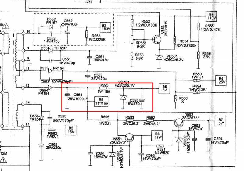
To know where the 5V supply comes from I would need to see the service manual, each TV model is different so I would need to see the schematic to trace which parts produce the voltage. I am not at a fast internet connection at the moment so I will search later to see if I can download it.

Brian.
 

Ok Thank you so much sir, I'll wait, Even I also searching LA76931S 7N 58Y4 schematic .....
 

Dear Brian Sir, Good Morning, Now Yesterday I checked the dc volt in EEPROM IC using multimeter with selecting knob to 200 v and 20 v red wire in 8th pin and black in 4th pin But, It's not showing any voltage. It's showing only Number 1 that'll al. now I got another problem, standby light is ON But, Not display and It's not showing the ERROR OF EEPROM ERROR, In crt tube neck there is no light (in yoke). please help me, what you'll suggest for me?
 

With over 600 components in that TV it's very difficult to make diagnosis over the internet!

However, the 5V supply should always be present on the EEPROM, even when the TV is in 'standby' mode so it may be a power supply fault. I think I have found the correct schematic and the components I would be suspicious of are in the red box:


They are:
C564 - 1000uF, 25V
C595 - 470uF, 16V
R595 - 180 Ohms, 1W
VD701 - Zener Diode 5.1V, 0.5W

Brian.
 

Ok Thank you so much sir, I will try this. one more thing I have to tell you, Yesterday my TV was ON we saw a movie. after that I switch off the TV, after sometime I switch on the TV only standby, No audio or video, I'll check components of as you said. Will you please provide me the full circuit schematic diagram.....?
 

Here it is, not very clear but usable.

Brian.
 

Attachments

  • KLX-S11Z LA76931-59F8, 58Z0, 58Y9 (N201).PDF
    1.6 MB · Views: 120

Om My God Thanks for your help.... I am really happy about your helping nature, I like you so much Sir, this is more than enough, I'll try with this one and I'll reply you on Monday(12/10/2015). Thanks Once again Brian Sir..... Thanks....!!!!!!!!
 

Dear SIr, I changed some capacitors then TV was came back to life. But, after closing the back cover the TV standby is ON, No raster (No video) What to do? I got help form a friend "he told me near the BIG IC there is a two pin crystal, short that then TV will getting ON". What a surprise the TV was ON, after switch off the TV and ON the TV its not ON only standby .... What to do ? How to check the voltage in transformer and flyback transformer using multi meter ? where should be black wire and red wire, what is the selected knob 1000v dc? Please Help me.... Sorry to disturb you again.
 

It could be a 'lazy' crystal but to be honest, there are many possible causes of intermittent problems like this. You could try changing the crystals (G201 and G701), just make sure you use ones with EXACTLY the same frequency or you will have all sort of strange problems. Bad crystals are very rare but I have seen them before. You could also try changing C729 which resets the big IC when the power is first turned on, if it's value changes it might either hold the IC in a reset state or release it from reset before it has become ready.

Please DO NOT measure voltages on the power or flyback transformer. Both have extremely dangerous voltages on them, so high that it can even spark through your multimeter probes to your hands. It can certainly damage your meter in a fraction of a second. It is very unlikely the are faulty, when they fail they normally stay dead forever.

Brian.
 

I don't see a power button in the schematic, so my question is:
Is your TV only turned on by the remote control? If so, do you have separate buttons for on and off? Your remote could be the problem. Usually the TV will remember last power state and power on until you tell it to power off.

Larry G
 

Dear Brian Sir, Thanks for your information , I changed some capacitors, vertical IC and horizontal IC after that the TV was On. Now it's not getting switch off again, and its working Normally after sometime also.... Now I got the another problem, That is the TV is showing more dark pink colour and its effecting our eyes. Is there any solution for the colour problem. I changed the degaussing coil also, but still the problem is there. even in the TV button (volume, program, menu & tv/av is not working), this is ok i'll change in remote. Now I have only the problem is in the pink colour problem . please help me.......
 

In old TVs the colors were adjusted by turning controls on the circuit board but newer Tvs like yours store the adjustments in the EEPROM. When you changed the EEPROM the adjustments were lost. If you still have the original IC it might be worth fitting it back in again as it was not the cause of the fault anyway.

Your other option is to use the service menu to change the settings yourself:

1. Enter the service menu and look for settings called Red-bias, Green-bias and Blue-bias. Ideally you need a plain black picture to do this - in a darkened room, adjust the three settings so you can *ONLY JUST* see the first signs of light from the screen. If you get it right all you will have is a barely visible gray screen.

2. Now display a normal picture (TV channel will do) and turn the color setting to minimum so the picture is black and white. Enter the menu again and adjust the Red-drive, Green-drive and Blue-drive so the brighter parts of the screen are gray without any color tint.

3. Repeat steps 1 and 2 because changing one setting may effect the other.

The bias controls set the black levels and the drive controls set the white levels so when you have them matched to each other, in theory, all the shades of gray between them will be the same. You can then turn the color up again to your preference.

Brian.
 

Dear Brian Sir, Thanks for your help. I couldn't see the RED bias, BLUE bias & GREEN bias in service menu, is there any loose contact in crt base board? or is there any colour IC in TV ? (as you said I replace the EEPROM IC original also but no use) Is there any other options? please help me.....
 

Here is my opinion while you're waiting for Brian. I used to service many CRT televisions. Dark pink might be the lack of Green signal which gives you Magenta which appears pink. Green also contains the most luminance so without it you lose brightness. Is the board on the CRT neck firmly seated into the tube?
Need to check the G path. N201 pins 12,13,14 (RGB) should be a DC voltage somewhere under 5V and G pin should not be 0v or low ohms resistance. My guess is a problem in the G path.

Larry G
 

I made the assumption that the TV was working properly before the 'power on' fault occurred but it is possible something else has been disturbed while works were carried out. The screen actually shows three different pictures overlayed on each other. One is red, one is green and one is blue. Together they create all the different shades you can see by altering the brightness of each picture relative to the others. When you see pink it can be an excess of red or more likely a lack of green which leaves red and blue predominant and gives a pink or purple tint.

The big IC controls all the colour levels, it has a brightness setting and a contrast setting for each colour. The brightness effects the level of dark and light areas of each colour and the contrast sets the gain or difference between dark and light for each colour. The normal user brightness and contrast settings change all three pictures at the same time. In technical terms, the individual brightness controls are called the 'bias' controls and the individual contrast settings are called 'drive' controls. Ideally, the bias controls are adjusted so the darkest parts of the picture are almost black and the drives so the brightest parts are white, that makes all the shades between them fall into line. Old TVs had mechanical controls to set the bias and gain but yours does it all inside the big IC. The settings are stored inside the EEPROM and read back into the big IC when the power is turned on. It follows that the only way you can make adjustments is by changing the values inside the EEPROM. That's what the service menu lets you do.

Somewhere, using the remote control, you can set the bias and drive levels. It's somewhere in the service menu but exactly where will depend on the individual TV manufacturer. The only way to be sure is read the full service manual which will contain the whole procedure for setting all the levels. The schematic, which is all I have, does not tell you how to do it but you must be very close to finding the settings as you have managed to activate the service menu yourself.

Brian.
 

In grid B4 is a switch XS406 and grid B3 a switch XP406 which is in the vertical drive circuit which might set up a service mode?
Is there a slide switch on the circuit board or on the back?
 

Dear Experts thanks to all !!!!!!!!!!!!!!!!
I got the problem that is ,the green colour is missing, that's why the TV coming like dark pink Larry said , that is correct. YES In the board on the CRT neck firmly seated into the tube, Now I got what is the problem, Now I need a solution, how to get green colour back again.? How to check the G path using multimeter? If you help me with image, that'll help for me and others also like my problem.... please help me my friends..... Thanks
 

XP406 is almost certainly to adjust the vertical drive, the same PCB is used in TVs with different sized CRTs, I would guess it works like a coarse height adjustment to cater for small or large screens. XS406 sets a positve or negative DC offset on the vertical scan coils so it would work as a coarse vertical shift control. In both situations, the fine adjustment is made using DACs inside the big IC.

Unless something got damaged while changing the other components, I still suspect it is a software adjustment using an incorect value from the EEPROM.

There are many components involved in producing the green part of the picture so it would be useful to find out if ANY of the picture is there at all. Please try this and tell us what happens:

1. With the TV unplugged from the power socket, unsolder one end of R908 and R928.
2. switch the TV on , the colours will not be correct! Do not leave it running for longer than necessary before reconnecting the resistors.

What we need to know is whether there is still any picture at all, you may see nothing or maybe a plain green screen or hopefully, an almost normal picture but only in green.
This type of TV uses what we call RGB drive which makes problem solving easier, your pink screen symptoms suggest the R and B are working properly but G has a fault. Knowing if anything at all is passing through the G circuits will help with diagnosis.

Please forget your multimeter, it is not the correct tool for most TV faults!

Brian.
 

Thanks brian Sir,
I'll forget about multimeter, I changed old (original) EEPROM IC as you said. but, the TV was not getting ON, only standby. After replacing new EEPROM IC the Has came back to life. But Now I am getting the problems of Green colour missing, How to check the G path? Is there any IC for colours? Will you please provide me the picture of RGB.
Should I change resistors and transistor in crt board ?
 

Please do as I asked in post #38 and tell us what you could see.

The colours are decoded from the incoming TV signal in the big IC then amplified to high voltages needed by the CRT by transistors. All the adjustments for the colour are held inside the EEPROM and I still suspect it holds some wrong numbers.

I'll try to explain: When you buy an EEPROM it is empty, all it's 2,000 storage locations hold zero. They are not a part only for a TV, they are used for many purposes in all kinds of equipment. When you turn the TV power on, the numbers stored in the EEPROM are read out of it and used to configure the big IC. Some numbers are for setting the RGB levels, some for holding the volume setting, brightness setting and even for holding the channel frequencies for your area. The trouble is, when you fit a new empty memory, you somehow have to put the correct numbers back in to it. The way that is done is through the TV service menu. I think the reason why the green part of your picture is weak may be nothing more than the numbers relating to the green settings are not correct or maybe not there at all.

You need to break the problem into smaller parts, do the tests I mentioned first, that will give an idea as to whether the number are wrong (the big IC is not configured properly) or there is a second electrical fault needing repair.

Brian.
 

Status
Not open for further replies.

Part and Inventory Search

Welcome to EDABoard.com

Sponsor

Back
Top