Continue to Site
Follow along with the video below to see how to install our site as a web app on your home screen.
Note: This feature may not be available in some browsers.
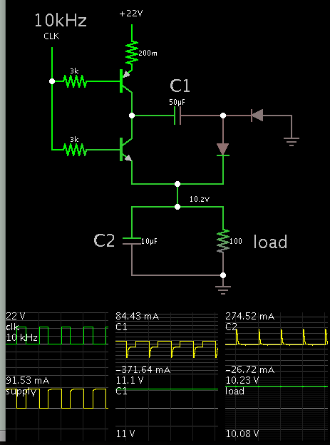
What is a way for 13V- 50V to 10V convertion?

What about capacitor divider?