Continue to Site

Welcome to EDAboard.com

Welcome to our site! EDAboard.com is an international Electronics Discussion Forum focused on EDA software, circuits, schematics, books, theory, papers, asic, pld, 8051, DSP, Network, RF, Analog Design, PCB, Service Manuals... and a whole lot more! To participate you need to register. Registration is free. Click here to register now.

Repair Realistic Color Organ - Missing Component

Status
Not open for further replies.

Sweetestbaboon

Newbie level 3
Joined
Sep 14, 2015
Messages
3
Helped
0
Reputation
0
Reaction score
0
Trophy points
1
Activity points
31
Hello wonderful electronic folks,
I'm a achoolteacher who was recently gifted a Realistic Color Organ. It's a really cool thing but alas & alack, it lights up but doesn't respond to sound at all (the lights are supposed to change with the music).
I saw this years-old thread & thought someone might be able to help a desperate schoolteacher!
The old thread is here, in case this helps to solve the problem:
https://www.edaboard.com/threads/254290/
I opened mine up & comparing my board to the one in the old thread, even to this layman, the problem seems obvious- the silver piece that modilates the the lights is simply missing. Here's a pic of my board:


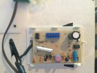
Can I get this part anywhere? Perchance do any of you much more experienced folks have an extra piece like this lying around you'd be willing to send to a deserving schoolteacher?
Even if I get the part, is it as easy as just putting in place? Is there somewhere or someone near me (I'm in Princeton Jct., NJ) that maybe could help?
Please help if you can. I know the kids would really dig this the most if I can really get it to work.
Thanks very very much for your time & consideration.
Enjoy the day,
Robt
 

How does signal reach the board? The older thread has a shiny disc-like object, which your board is missing. I believe it is a microphone.

Is there a cable connection for an incoming signal? If not then I think you need a microphone. And there may be more work still needing to be done.
 

Thanks so much for your reply. Yes indeed, if you look at the board in the original thread & then compare it to mine, the mic is the missing component. So
I guess I need to find that (anyone? Anyone? Pretty please?) & then do you think it just pops in. There is no cable coming from board except what goes to lights to power them & there seems to be nothing else missing...
Please help!
Thanks again!
 

If you are very lucky, no other component is damaged. And if you are very lucky, no high voltage is getting where it should not.

If we were Sherlock Holmes, we would try to figure out why anyone would yank the mic off the board and pull out two wire leads. Suppose they wanted to scavenge the mic for another project, but they probably ruined it. Perhaps it was deliberate, to render the board useless, maybe after someone got a high voltage shock from it.

First you should measure with an AC voltmeter, to see if high voltage is present. Measure across the mic's exposed wire leads. Measure across various points on the board. I believe high voltage should be present only among components at the upper left corner of your photograph.

If you can attach any kind of mic, that might be all it needs to make it work. It might be a dynamic element, or carbon, or even a small speaker as from a headphone or transistor radio.

The signal might come from any device which produces audio. An amplifier, Ipod, phone, computer, etc. This is where you have to know something about safe interconnecting practices. You don't want to destroy a good device.

If you get nothing, then you will need to diagnose the board further. Make sure it is getting power. The proper voltage. Etc.
 
Thanks again for staying with me.
Forgive me but I am a complete novice here.
How woyld I go about connecting such a device to the board?
Thanks!
 

Small jumper wires are the handy item for this. Your local Radio Shack should have these (if a store is still operating near you).

Image grabbed off the internet:


But what if you want to get audio out of the jack of a radio or Ipod? Clips aren't able to do this. Usually this requires a 1/8 inch phone plug (or maybe 3/32 inch). Maybe mono, maybe stereo. A stereo plug will cover all circumstances.

------------------------------------------------

As a test, you can try applying voltage from a battery, through a high ohm resistor. Just one more thing to try and see if it will light up. A 1.5V cell and 3-10 k ohms might be all right. Try applying one polarity across the exposed leads for a tenth of a second. Then the opposite polarity. Etc. Nothing says this will work, since the unit was probably designed to accept an AC signal.

Only you can decide how much money you want to spend on this.
 

Looking at the PCB in the previous posts, I urge caution about the placing of the plugs on that socket. The plugs can be moved along in different positions and if wrongly inserted it can cause significant damage. Regardless, it has no isolation from the incoming power lines so unless there is a transformer (a wall wart maybe) between it and the wall socket, it could be extremely dangerous. I can't see any high voltage components so it probably runs on low voltage AC and drives flashlight lamps.

Essentially, it's a single channel sound to light converter and the missing part is almost certainly a dynamic microphone. It could be an electret type but the board is dated 1978 which is before they became popular.

Brian.
 

Status
Not open for further replies.

Similar threads

Part and Inventory Search

Welcome to EDABoard.com

Sponsor

Back
Top