Continue to Site

Welcome to EDAboard.com

Welcome to our site! EDAboard.com is an international Electronics Discussion Forum focused on EDA software, circuits, schematics, books, theory, papers, asic, pld, 8051, DSP, Network, RF, Analog Design, PCB, Service Manuals... and a whole lot more! To participate you need to register. Registration is free. Click here to register now.

How to identify a broken zener diode?

Status
Not open for further replies.

Choose

Newbie level 6
Joined
Sep 12, 2015
Messages
14
Helped
0
Reputation
0
Reaction score
0
Trophy points
1
Location
Leon, Spain
Activity points
141
Hello all. This is my first post. I will try to be as brief as possible:

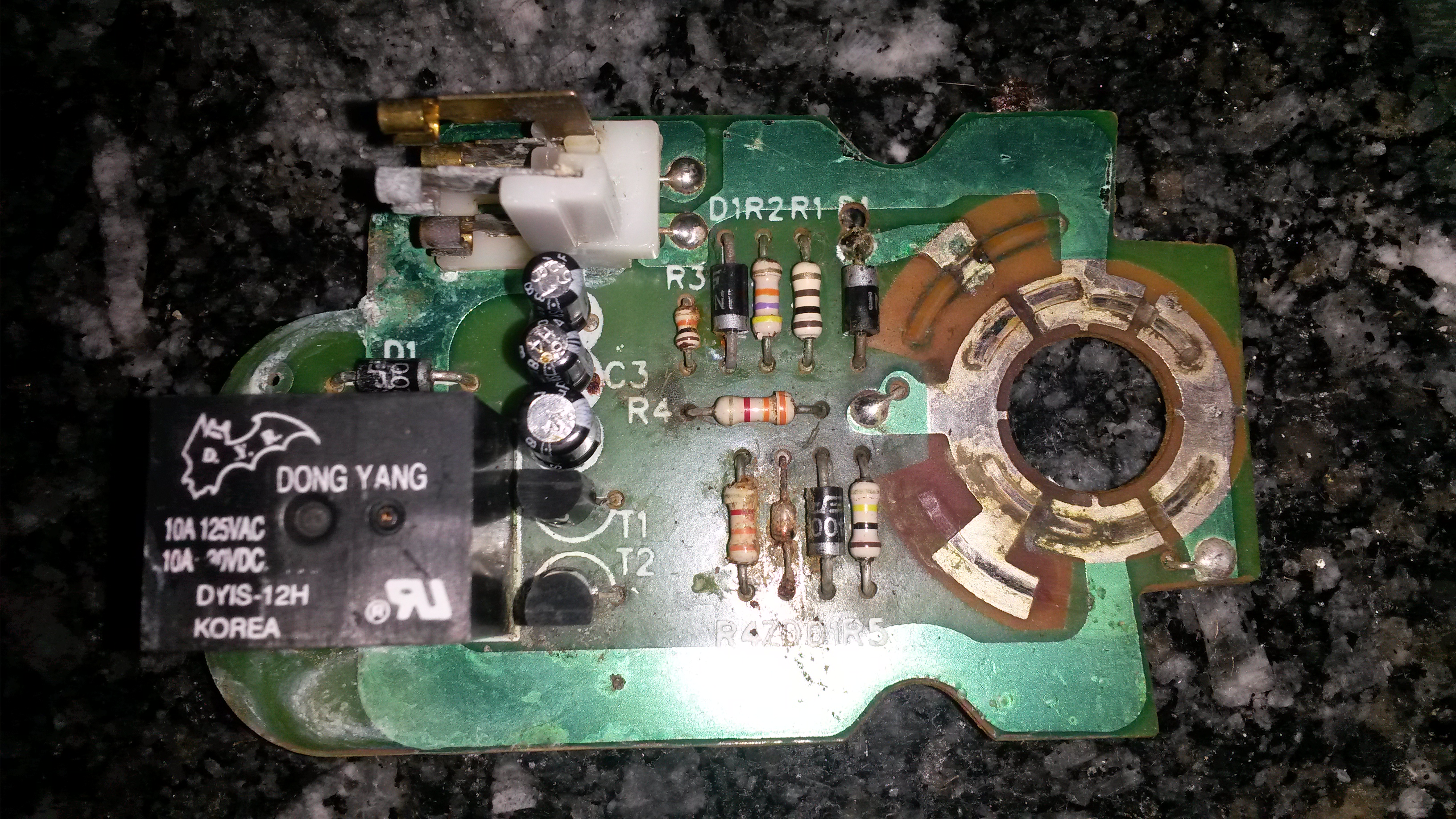
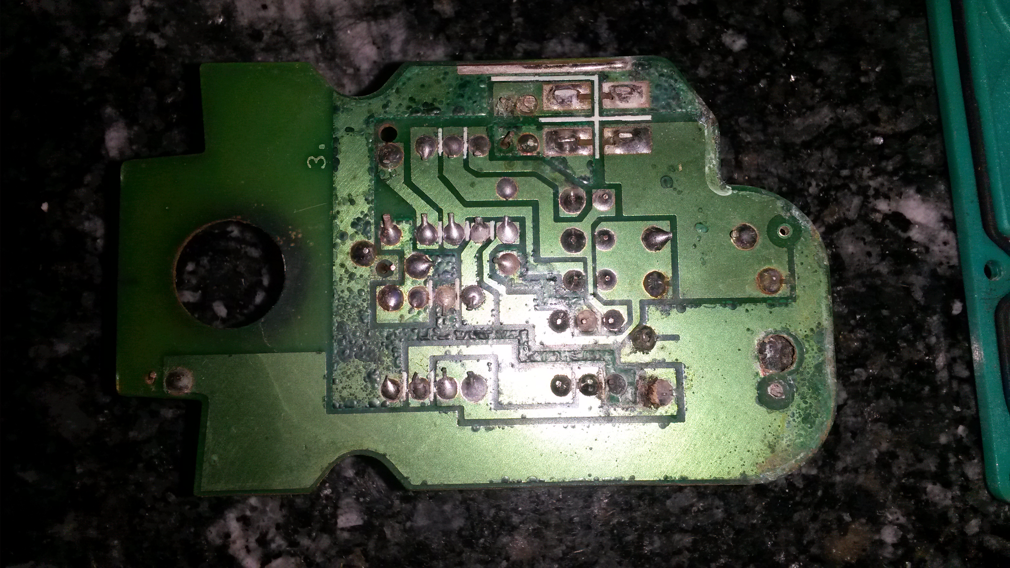
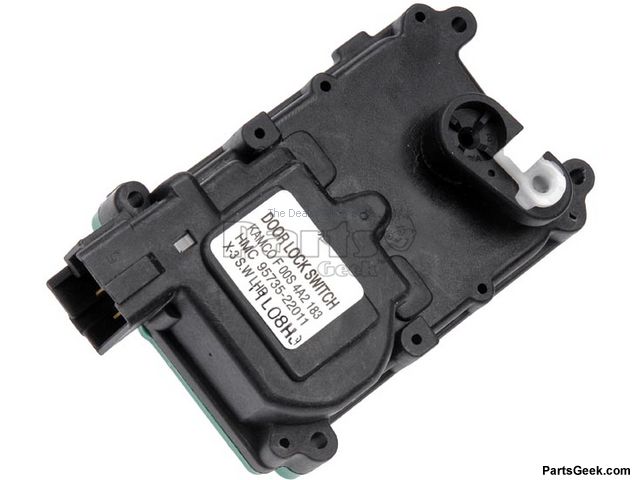
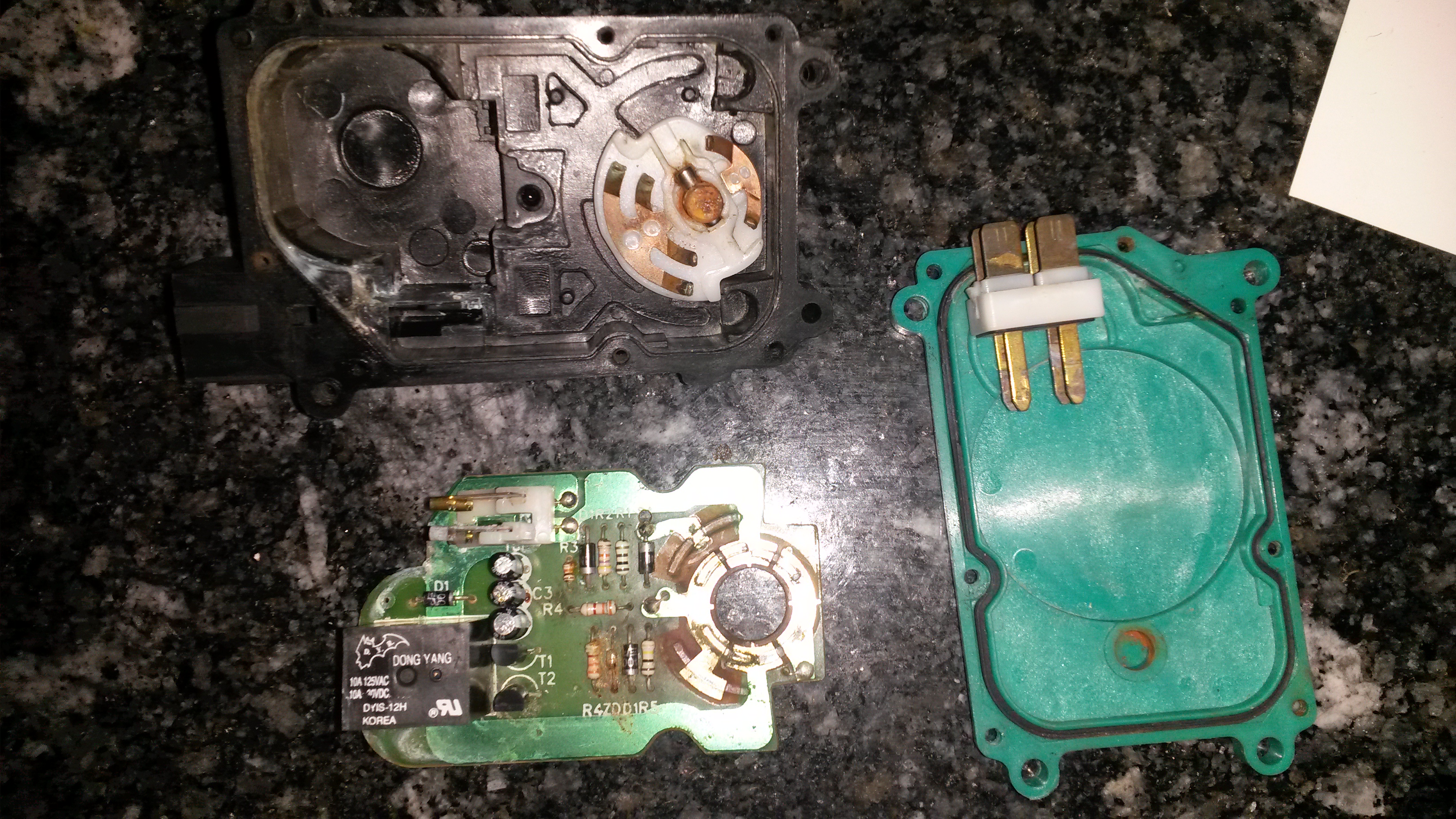
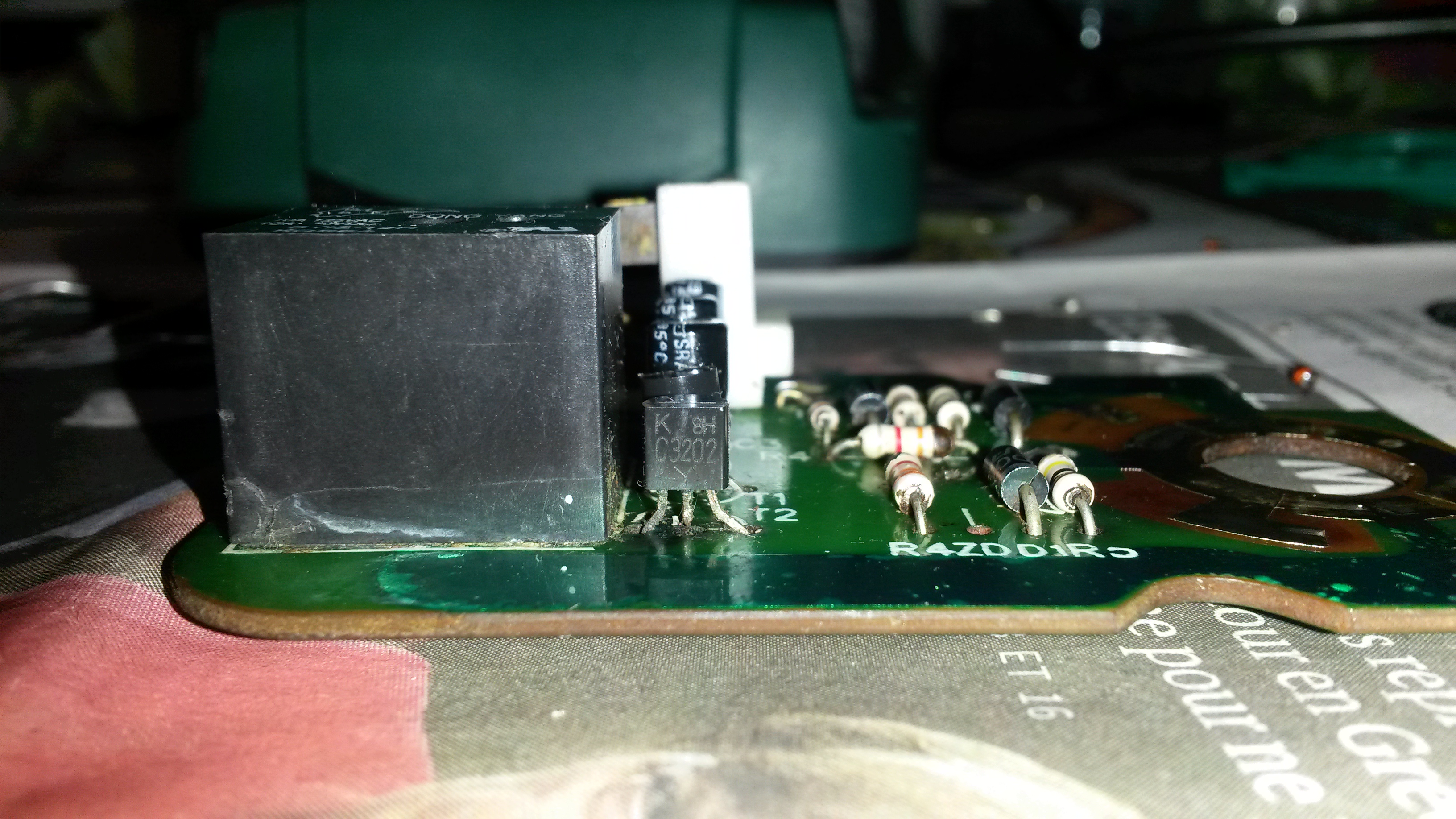
I am awkward at electronics, but nevertheless I don't give up and try to fix some little things. This time I have found that the door lock switch of my '98 Hyundai Accent has been damaged by water (sealing issues). I used Wurth Contact OL to remove rust but one of the components of the board has got broken while I was trying to remove the rests of the product with a piece of paper. I believe I can carry out the soldering work but I cannot identify the broken component. My searches (and the letters printed on the board :cool: ) lead me to believe it is a zener diode, but what kind? There are no markings on it.

I have thought about asking the local shop to give me a selection of the most common types and go the trial and error way, but I am afraid I could fry other thing... So, could someone guess, by the pictures of the board, what kind of component I need to have all the doors of my car closed in one move like in the old good times?


Have you checked the opposite door for an identical board?
 

One diode shows 1N and another shows 400 so they all might all be the same common 1N400x rectifier diode.
 

Have you checked the opposite door for an identical board?

Unfortunately this car has only one lock switch actuator in the driver's door. The other doors have only "slave" mechanisms that are different from this one.

I might look in a scrapyard, but it is not common anymore to find cars of this model. It is becoming a classic. ;-)
 

One diode shows 1N and another shows 400 so they all might all be the same common 1N400x rectifier diode.

It is my fault: I haven't specified which component is broken (these pictures were taken BEFORE the cleaning process).

The diodes you mention are still in good visual condition and fortunately they do have markings. The supposed diode I am trying to identify is the tiny one, second from the left in the bottom line of four components (between a resistor and a standard diode). The flash of the camera has masked the marking on the board, but it reads "ZD", which I take for "zener diode". That is all I know about it. Pictures I found on my searches more or less confirm my assumption. The bottom lead of this component vanished into dust.
 

I have no idea how your board works, so I decided how it might be designed and came up with something that uses similar parts.

The zener performs 2 tasks.

1) protect the reverse bias of the transistor from breakdown.
2) allows a reverse bias to control the 1 shot stop duration.

If the Vebo rating is -6V like a pn2222 NPN then use a 5.6V or 4.7V zener

If you can see the cathode bar, then you know orientation.

my rough design will latch a relay for xxx ms regardless if the switch is held down for 10 seconds or 1 ms. So there are 2 cap/diode/R timer 1-shots

latch.jpg

ignore my actual RC values and 14V comment and use 4.7 or 5.6V zener

top trace is arbitrary relay coil current
bottom trace is switch voltage seen on Q1-Vbe

this board looks like it would about $0.30 to produce in volume including board with no PTH. maybe $0.70 with inflation over last 15 years. I am alwaso surprised at the poor quality standards on this board . No conformal coating. Chrystler would never let us do that.
 
  • Like
Reactions: Choose

    Choose

    Points: 2
    Helpful Answer Positive Rating
Did you try measure it with a digital multimeter (diode test mode)? It should measure as a diode. If yes, then you can disconnect it from the board and find out what the zener voltage is.
(You add in series a 10KΩ (KOhm) resistor, supply 15 to 24Vdc in reverse polarity and measure the voltage on the diode edges).
 

Wow SunnySkyguy, you left me speechless... I post here a picture of all the components in case it is useful for someone, and a picture of the Hyundai part where you can see the P/N on the sticker. The sticker on mine didn't resist time and water weathering... Luckily the Stone Age folks preferred carvings...

I will do as you suggest and get some 5,6V ZD. I will lose one, break the second, drown the third in a huge ball of stain and hopefully put the fourth in place.

The switch is part of the black case. It is the white plastic thing with some copper contacts on it. It works by a 1/4 turn. I believe that this device sends a +/- shot to a relay somehere under the steering wheel, which in turn sends its own +/- shot to the slave devices in the other doors.


There's 50/50 chance my guess is completely wrong. A good DMM should have a diode tester.

Start by checking voltages in diode test mode (mV) or resistance.

Then see if you can determine which part anode and cathode is connected to. B , C or E of a device and if that device is NPN or PNP

That will improve your odds of a better answer

with the plastic case, the volume mfg cost rises to $1.50 which means in a auto parts depot, it will cost you $150 or so.

try a scrap yard, "Pick-a-part " take tools.
 

You have to desolder component before checking with multi meter, some time component do not show their property when they are in circuit.

Open Diode

If a zener diode reads high resistance in both directions, this is a sign that the diode is open.

Shorted Diode

If the zener diode reads low resistances in both directions, this is a sign that the diode is shorted.

The diode is definitely out of order as the bottom lead (not sure yet whether it is the anode or the cathode) has disappeared after cleaning the rust. Anyway I have found this link that might be useful for testing zener diodes, as it seems they are always paired to a resistor: http://www.learningaboutelectronics.com/Articles/How-to-test-a-zener-diode

I don't think I can use this method as rust has attacked the core of the diode... But it might be useful for someone.

It's the 1st time I have seen silkscreen REFDES for a unique part number rather than a unique location. easier for hand stuffing...

If you mean that auto parts use to have engraved IDs, I totally agree. I have a certain experience with VAG parts (Volkswagen-Audi Group) and the P/N use to be much more "solid".

Every time I disassemble a part of the Hyundai, stickers fall like leaves in autumn.
 

REFDES means Reference Designators meaning R1`, R2 etc
It's the 1st time I have seen silkscreen REFDES for a unique part number rather than a unique location. easier for hand stuffing...

There are two R4's both 33K
There are two D1's , same diode

Now, I can tell the transistors are different because they are labeled Q1, Q2

YOu may have to trace schematic and parts shown on board.
 

REFDES means Reference Designators meaning R1`, R2 etc


There are two R4's both 33K
There are two D1's , same diode

Now, I can tell the transistors are different because they are labeled Q1, Q2

YOu may have to trace schematic and parts shown on board.

:oops: I am sorry... I was too lazy to Google it... Bad guess...

Before learning how to trace a schematic, I will take my chances. I have just bought some 3.9, 5.1 and 5.6 zener diodes. Time for some desoldering work. Hmmm... I will take the middle way...

If on the News you hear about a giant blast that has turned the north of Spain into a zombie playground, then you'll know it didn't work. :wink:
 

Well, here is the update. Tested the 5.1 zener on both senses (I am not sure of the polarity... the old one has no markings and acts as shorted according to the multimeter). Much to my dismay, none of the setups worked. Then I noticed something:


The transistor on the picture is damaged too. The middle lead is corroded and don't make contact with the board. Time to go back to the shop hoping they have something similar. It's discouraging when you don't have much idea of what you are doing... Well, I will post the end of the story; someone could find it useful.
 

This is a general purpose NPN transistor
https://www.rct.ru/pdf/transistor/2sc3202.pdf
The corroded middle leg (probably the Collector), is not a prove of it to be damaged.
You could use the diode test mode in a multimeter to test it (it should appear as two diodes with common leg the Base ie the right leg as we see it in the picture you posted).
If you acknowledge that it's functioning, then you could bend it a little so the short leg, touches the copper pad and can be soldered.
 
  • Like
Reactions: Choose

    Choose

    Points: 2
    Helpful Answer Positive Rating
Thank you for the explanation and the idea, xenos. I have searched for a compatible part and found some references. The shop guy told me he could have some BC 338 for me in a couple of days, so I will give one of them a try. I think the C3202 is far too much corroded to keep it there, and it is a potential source of problems (and confussion).

As I lack most of the necessary lab equipment (and especially skills) it is a hassle to try the device after every test. I must plug it in place and see if it works, and the car is parked somewhere around, three floors down.

Ah, the DIY wannabes... :roll:
 

Be very careful when you place the BC in place of the 2SC. The legs are not in the same ordering. You will have to bend legs or rotate transistor accordingly.

The images in the link are just examples and not the actual solution. See the order of pins in the two datasheets and act as required:
**broken link removed**

...The shop guy told me he could have some BC 338 for me in a couple of days...
You have to wait for the bc338? I wonder what would happen if you have asked for a rare component...:thinker:
 
  • Like
Reactions: Choose

    Choose

    Points: 2
    Helpful Answer Positive Rating
Be very careful when you place the BC in place of the 2SC. The legs are not in the same ordering. You will have to bend legs or rotate transistor accordingly.

The images in the link are just examples and not the actual solution. See the order of pins in the two datasheets and act as required:
**broken link removed**


You have to wait for the bc338? I wonder what would happen if you have asked for a rare component...:thinker:

Thank you very much for making me notice the differences... To my understanding (and confort), a replacement part must be some kind of "plug and play", but I see that I cannot take it for granted. The C3202 has an Emitter/Collector/Base schema, while the BC 338 seems to have a Collector/Base/Emitter design. Reverse positioning and two-legs careful twisting will have to make it...

I am used to suffer this zero-stocks policy in many fields here. I can even say I am lucky to have it here tomorrow. Many times it is easier and faster to search on eBay or to order abroad.
 

Well, I have had some time for testing and I am about to give up. I have put the transistor in place, properly altering the order of the leads. I have tested all the resistors and the diodes and they seem to be ok. The 5.1 zener diode has been in place in both ways several times. All I get is a random short relay clicking, and then nothing at all.

When testing voltages I get that the part of the circuit that did not suffer damage keeps almost 12V everywhere (including the other transistor, no visible markings on it but acting like a PNP). On the other hand, the side I "touched" reads 5.15V. Moving the switch makes no difference.

My common sense would tell me that the whole circuit should work at 12V and the switch should allow to decide the path that acts on the relay; I could conclude that it is the 5.1V ZD that is conditioning the reads and that I should think about a higher flavor of this component... It is my last guess before taking the tour of salvage yards around (yesterday I visited one with no luck). I assume the relay is ok...

If you believe I should not bother to buy a 12V ZD I will use that time for better things. Thank you anyway for all your help.
 

Status
Not open for further replies.

Similar threads

Part and Inventory Search

Welcome to EDABoard.com

Sponsor

Back
Top