viperpaki007
Full Member level 5
Hi,
I want to simulate NF values of an ideal amplifier. For modeling amplifier noise, i have put a noise voltage source in series with amplifier input and noise current source in parallel to amplifie input. The sources take the spectral noise density values in Volts squared per Hz and Ampere squared per Hz. I am using the following formula to calculate the spectral noise density voltages and currents.
(10^(NF/10))*10^(-174/10)/1000 This should give the noise spectral density in Watts/Hz
As P=I^2*R, For Current source, i divide this Watts/Hz value with Source impedance Rs to get Ampere squared per Hz and for voltage source i multiply this Watts/Hz value with Source impedance Rs to get Voltage squared per Hz.
If i plot the NF after that. It does not give me the right value. Can somebody suggest what values i should put in sources which give me corret NF value. Am i doing the calculations right?
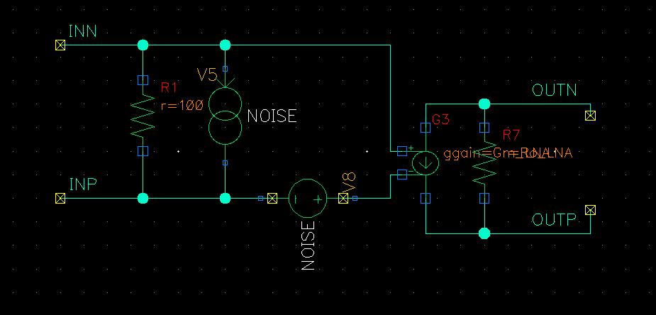