Continue to Site

Welcome to EDAboard.com

Welcome to our site! EDAboard.com is an international Electronics Discussion Forum focused on EDA software, circuits, schematics, books, theory, papers, asic, pld, 8051, DSP, Network, RF, Analog Design, PCB, Service Manuals... and a whole lot more! To participate you need to register. Registration is free. Click here to register now.

[SOLVED] First project with Atmega328P -108mA for blinking one led.

Status
Not open for further replies.

lachmannmarcel

Junior Member level 3
Joined
Jan 15, 2011
Messages
29
Helped
1
Reputation
2
Reaction score
1
Trophy points
1,283
Location
Romania
Activity points
1,431
It is my first project using Atmega328P. I try to clone Arduino Uno and make my board(see atach). I upload blink.ino and my power source show 108mA.
And micro become hot. The led is blinking but 108mA is to much.
What i done wrong?
PS: in schematics i have two R3 but PCB is ok, they are not one but two resistors with good conections. schema.png
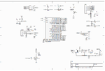
 

You cannot directly sink 108ma on any pin of the Atmega328 microcontroller. This will naturally damage the port. You may trigger the gate of any N channel mosfet like IRF840 with the Microcontroller pin and then drive the said load with the drain of the the mosfet.
 

I don't see a led in your schematic, just a LEDPWM line.

Have you used a resistor in series with the led?
 

I don't see a led in your schematic, just a LEDPWM line.

Have you used a resistor in series with the led?

Nokia 5110 have 4 led. LEDPWN go to 100ohm pot.

- - - Updated - - -

The entire schematics consume 108mA. Not one port. And i want to now why.
 

According to https://learn.sparkfun.com/tutorials/graphic-lcd-hookup-guide the display works with 3v3 supply but you have used 5v (according to your schematic).

100 Ohm for 5v is on the low side for four leds in parallel I think you should increase the resistance to 240-470 Ohm (unless you reply on the PWM duty to limit the current).
You can easily check the current they use by disconnecting them and measuring the drop in current draw.
 

I remove the Nokia 5110 and the consumtion varied with a few mA. All the time the nokia led where off(i intend to use pwm on them)
 

How about the supply of the LCD , do you use 3.3v as the specs state (between 2.7V and 3.3V actually) ?
 

Were you ESD safe?

Why are LEDs shown backwards?

Each output is 25 Ohm nominal ESR so if shorted to gnd or supply and active in opposite state , current limit from 3V is 120 mA !!


I calculate ESR as follows. ( actually internal RdsOn)

ESR = Vol/Iol and (Vcc-Voh)/Ioh

- - - Updated - - -

Many kits run from 5V
https://www.ruggedcircuits.com/10-ways-to-destroy-an-arduino/
 

Please help me understand.
Electrostatic discharge (ESD)?
ESR google say Erythrocyte Sedimentation Rate?!?
On schematics led are backwards, on pcb they are put right.
The led on D13 work, the Nokia work BUT power absorbtion is to high. What mistake i made on schematics?
 

Pin 7 dont have voltage. Only AVCC. After i connect pin 7 to Vcc everething come to normal(16 mA total consum).
 

Status
Not open for further replies.

Part and Inventory Search

Welcome to EDABoard.com

Sponsor

Back
Top