thannara123
Advanced Member level 5
Anybody Know very-good Pure-sin-wave Inverter Technology transfer . With latest technology and reliable with low cost .
Follow along with the video below to see how to install our site as a web app on your home screen.
Note: This feature may not be available in some browsers.
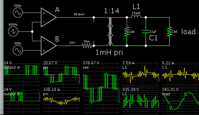
A quick sim will convince you that if you want 50/60Hz to come out of a Tx, then that Tx does handle all the 50/60Hz energy...
very-good Pure-sin-wave Inverter Technology transfer . With latest technology and reliable with low cost .
sorry Brad, for a 1kVA inverter using a 50/60Hz transformer, the transformer rating must be 1kVA no matter how the fundamental is generated...there is no saving...
1) to a set of 4 fets running off a 350V bus, to provide the desired Vac out, needs to be filtered to remove the sw freq, and,
2) on a low volt set of fets intended to drive a transformer to get 230Vac (for eg) at 50/60Hz
There is one partial exception, say you have a forward converter (or any converter really) and you modulate the output so that it makes positive half sine waves at its o/p, 0 - 325 - 0 - 325...etc then feed this to an H bridge and use the switches to "unfold" this to your load (the mains) so that it matches the mains polarity.