Continue to Site

Welcome to EDAboard.com

Welcome to our site! EDAboard.com is an international Electronics Discussion Forum focused on EDA software, circuits, schematics, books, theory, papers, asic, pld, 8051, DSP, Network, RF, Analog Design, PCB, Service Manuals... and a whole lot more! To participate you need to register. Registration is free. Click here to register now.

[SOLVED] electrostatics thought experiment question

Status
Not open for further replies.

jmvalks

Newbie level 5
Joined
Aug 13, 2011
Messages
10
Helped
0
Reputation
0
Reaction score
0
Trophy points
1,281
Activity points
1,416
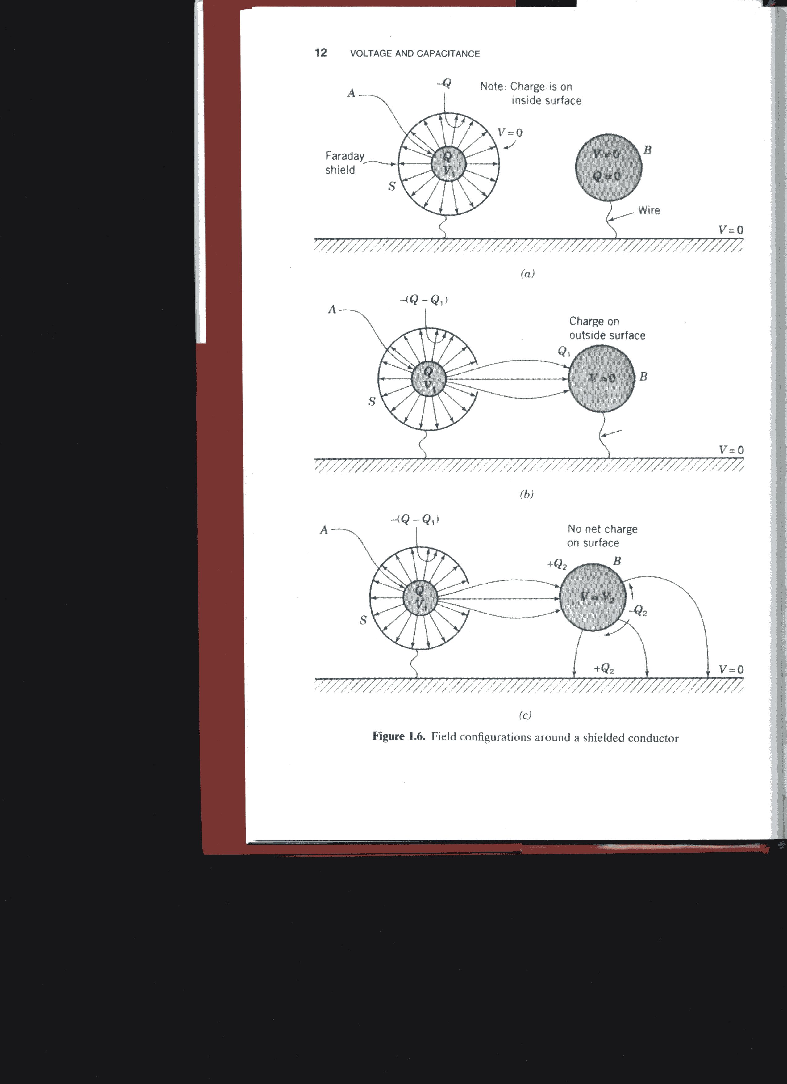
I am reading Ralph Morrison's book Grounding and Shielding: Circuits and Interference, 5th ed. and in the section on electric field patterns he has a conductor, A, containing a charge (charge Q at potential V1) completely surrounded by a shield, so no electric field escapes. This screen is attached by a wire to a ground plane (VB = 0).

He then has two similar situations, with a small hole in the screen surrounding A that lets some of the charge from A terminate on a nearby conductor, B, connected to ground by a small wire, and on a conductor, C, floating (not connected to ground) at a potential V2. He goes on to say there is a charge distribution on both B and C, but that C has a zero net charge, as some field from C is terminating on the ground plane, and also that C is not at ground potential; whereas B has a net charge but is at ground potential.

My questions are:
Why is there a charge distribution at all, when I would expect the charge to be evenly distributed along the surface of conductors B and C?

Why should there be no net charge on C, i.e., why should there be sufficient negative charge on C causing an electric field to terminate on the ground plane sufficient to balance that caused by the field terminating on C from A?

I hope all this makes sense.

Thanks,
JMV
 

To follow your verbal description is difficult, but it reminds me of the operating principle inside vacuum tubes.

There's the grid, which is placed between two terminals. Depending on the grid charge, it inhibits or promotes electrical action between the other terminals.

The theory sounds simple but there are doubtless details of manufacturing that require additional explorations of theory, just to make it work in real life.

Anyway I thought a bit of vacuum tube theory might assist your thought experiment.
 
Hi BradtheRad

The vacuum tube is an interesting analogy and probably is similar to the original problem in that there are conductors in proximity to one another and the device relies heavily on electric fields (the grid is at a negative potential relative to the cathode to prevent, rather than assist, the flow of electrons, rather like the action of a JFET.

I think my specific problems are conceptual ones.


In the first case, I have failed to understand why there should be a concentration of charge on the second conductor at a position adjacent to the first: why does not the charge distribute itself around the conductor rather than remaining concentrated as described?

In the second case, why should some of the field lines terminate on the ground plane sufficient to balance the charge induced by the first, almost screened, conductor.

Thank you for adding the vacuum tube to the mix. This sounds like a realistic example of what the author of the book is probably discussing.
 

To change the net change of a conductor, there must be current flow into or out of it. That's possible for B but not for C. So if C has intially zero charge, it will keep it forwever. Instead the potential of C will change according to the surrounding field.

It would be better to have a simple problem sketch.
 
I have scanned the relevant pages from the book. Unfortunately I cannot attach them. Apparently I need to be in the New Post page but I cannot fin the Post Reply button.

When I have sorted this out I will attach the file.
 

The attachment I have is a pdf file. From the content one of the forum messages it seems I cannot do this from the Quick Reply screen. Is there any other way I can do it?
 

Try the 'Manage attachments' button.

Edaboard provides each member with an area to store his files. These can be text, images, pdf's, zip, etc.

Clicking the button opens your collection of attachments. You can upload files individually, then add them to a post.
 

I attach the illustration from the book which I hope will clarify my lengthy description.


Status
Not open for further replies.

Similar threads

Part and Inventory Search

Welcome to EDABoard.com

Sponsor

Back
Top