Continue to Site

Welcome to EDAboard.com

Welcome to our site! EDAboard.com is an international Electronics Discussion Forum focused on EDA software, circuits, schematics, books, theory, papers, asic, pld, 8051, DSP, Network, RF, Analog Design, PCB, Service Manuals... and a whole lot more! To participate you need to register. Registration is free. Click here to register now.

Crystal load capacitance?

Status
Not open for further replies.

samy555

Full Member level 4
Joined
May 11, 2010
Messages
207
Helped
0
Reputation
0
Reaction score
0
Trophy points
1,296
Location
Palestine
Activity points
2,963
Hi
From page 1.17 of:
fig1.jpg
I read:
fig2.jpg
fig3.jpg

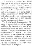
The author says: "Our crystal had marked frequency of 7045 KHz. This was the specified frequency for operation with a 32-pF load capacitance."
My question is: If I had a 20MHz crystal, how will I know the exact value of its load capacitance?
Thank you

fig4.jpg
 

The load capacitance is what you specify when you get the crystal made. Ready made crystals will have the load capacitance specified for their frequency and you would design your circuit to match that capacitance. The frequency moves slightly as the capacitance changes, that's why its necessary to know it.

Brian.
 

Hi,

Usually you find the capacitor value in the crystal datasheet.

Klaus
 

I think students do not look at the datasheet for anything because the electronic parts are cheap junk bought on ebay with no manufacturer's name and no datasheet.
 

....... because the electronic parts are cheap junk bought on ebay with no manufacturer's name and no datasheet.
Yes, you're right
What do you do if you were this student?

fig5.jpg

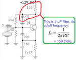
Q2: For the RC LPF shown above, is it important to have a frequency of 159KHz, or it is not critical?

Q3: Is that oscillator a common collector colpitts oscillator?

thank you alot
 

Q1. Buy parts from a reputable supplier. If that isn't possible, the best you can do is make a guess, most Quartz crystals are designed around 15 - 30 pF load capacitance.
Q2. Almost certainly it isn't critical, the values only determine the impedance at the collector. The capacitor is essentially keeping the collector at ground signal level and the resistor is providing a degree of signal isolation from supply line noise.
Q3. Correct.

Brian.
 
  • Like
Reactions: samy555

    samy555

    Points: 2
    Helpful Answer Positive Rating
Q1. Buy parts from a reputable supplier. If that isn't possible, the best you can do is make a guess, most Quartz crystals are designed around 15 - 30 pF load capacitance.

Q3. Correct.

Brian.
Excellent answers, I benefited a lot of them, Thank you Brian.

Q2. Almost certainly it isn't critical, the values only determine the impedance at the collector.
OK
The capacitor is essentially keeping the collector at ground signal level
Xc of that 10n capacitor @ 7MHz = 2.27Ω ,, yes short circuit
and the resistor is providing a degree of signal isolation from supply line noise.
How???? it is very small value?
thanks
 

Q4: (Repeated): For the RC Low Pass Filter shown below, is it important to have a frequency of 159KHz, or it is not critical?
broken link removed

Q5: the base voltage (VB) = 6 volt, VE=5.4 volt (if VBE=0.6 V),,, IC = VE/RE= 2.45 mA
I think that IC is relatively large and the circuit designer could accomplish the same performance if he work with 1mmA or even 0.5mA. Do you agree with me in this opinion?

thank you very much
 
Last edited by a moderator:

The RC combination is an optional power supply filter, intended to remove switching noise or RF signals generated by other parts of the circuit. Dimensioning isn't critical at all, in case of doubt, you'll use a larger capcitor to imoprove the filter effect.
 

Q5: the base voltage (VB) = 6 volt, VE=5.4 volt (if VBE=0.6 V),,, IC = VE/RE= 2.45 mA
I think that IC is relatively large and the circuit designer could accomplish the same performance if he work with 1mmA or even 0.5mA. Do you agree with me in this opinion?

Sure. But it depends on the input capacitance of the stage which receives the oscillation power from the emitter output. With too large input cap, oscillation might not start. Should be worst case, corner and - if possible - MC simulated.
 

Q4: (Repeated): For the RC Low Pass Filter shown below, is it important to have a frequency of 159KHz, or it is not critical?
broken link removed

Re the 100 ohm resistor:

Playing with simulations I have seen values work from 100 to 1000. It provides some degree of isolation between the oscillating loop and the power supply, so the oscillating loop can exhibit wider voltage swings.

Q5: the base voltage (VB) = 6 volt, VE=5.4 volt (if VBE=0.6 V),,, IC = VE/RE= 2.45 mA
I think that IC is relatively large and the circuit designer could accomplish the same performance if he work with 1mmA or even 0.5mA. Do you agree with me in this opinion?

Those are in the range of reasonable levels. It is usually possible to adjust a value or two somewhere, and get the circuit to oscillate. You might adjust the bias current, or supply voltage, or emitter resistor, collector resistor, etc.

Some of it depends on the characteristics of the real transistor you use.
 
Last edited by a moderator:

The RC combination is an optional power supply filter, intended to remove switching noise or RF signals generated by other parts of the circuit. Dimensioning isn't critical at all, in case of doubt, you'll use a larger capcitor to imoprove the filter effect.
I mean from the very beginning that the frequency of 159 KHz is far away from the operating frequency (7MHz) and also far away from the electricity humm (50/100 Hz).
Is the 100Ω resistance and 10 nF cap are a low pass filter or not?

thank you very much

- - - Updated - - -

Sure. But it depends on the input capacitance of the stage which receives the oscillation power from the emitter output. With too large input cap, oscillation might not start. Should be worst case, corner and - if possible - MC simulated.

Sorry do not tell me about things that can not be calculated! can you calculate the input capacitance of the stage?

Then what is the relationship between current and input capacitance?
thanks alot

- - - Updated - - -

Re the 100 ohm resistor:

Playing with simulations I have seen values work from 100 to 1000. It provides some degree of isolation between the oscillating loop and the power supply, so the oscillating loop can exhibit wider voltage swings.


Those are in the range of reasonable levels. It is usually possible to adjust a value or two somewhere, and get the circuit to oscillate. You might adjust the bias current, or supply voltage, or emitter resistor, collector resistor, etc.

Some of it depends on the characteristics of the real transistor you use.
I'd expect better answers than those you have given me like tell me that the filter must have frequency ranges between X & Y.

Oscillator can not work with weak currents like 0.5mA, or there is no difference between the use of 1mA or 3mA.
Thank you very much.
 

Is the 100Ω resistance and 10 nF cap are a low pass filter or not?

Yes, as we repeatedly stated, it is to let clean DC reach the oscillator from the supply line so it doesn't risk being modulated by supply line noise. The capacitor also keeps the collector at (very close to) ground from the oscillation perspective.

Do not read too much into the 159KHz figure, it is not relevant to the oscillators function, the values were chosen as 'mid-range' suitable ones rather than being calculated for a specific cut-off frequency. Personally, I would probably add an additional capacitor of 1uF to 10uF across the 100nF for even better supply rejection.

Brian.
 
  • Like
Reactions: samy555

    samy555

    Points: 2
    Helpful Answer Positive Rating
Sorry do not tell me about things that can not be calculated! can you calculate the input capacitance of the stage?
Not exactly calculate, but at least I can estimate the input capacitance of the next stage. Or even better: analyze it by simulation!

Then what is the relationship between current and input capacitance?
The current determines the emitter output resistor, by this the output capacitance of the oscillator stage to the next stage. Lower current needs higher resistance, so generates higher output impedance. This - on the other hand - determines, if the output impedance is low enough to drive the input impedance of the next stage. If this isn't true, the oscillator won't start oscillating. Try it by simulation!
 

Yes, as we repeatedly stated, it is to let clean DC reach the oscillator from the supply line so it doesn't risk being modulated by supply line noise. The capacitor also keeps the collector at (very close to) ground from the oscillation perspective.

Do not read too much into the 159KHz figure, it is not relevant to the oscillators function, the values were chosen as 'mid-range' suitable ones rather than being calculated for a specific cut-off frequency. Personally, I would probably add an additional capacitor of 1uF to 10uF across the 100nF for even better supply rejection.

Brian.

Thank Brian,, the following question directed to you personally:
If you want to re-design this osillator for working at a frequency of 100 MHz, What are the new valuse you choose for the 100Ω and 10nF?
Greetings

- - - Updated - - -

Not exactly calculate, but at least I can estimate the input capacitance of the next stage. Or even better: analyze it by simulation!

You and I know that simulation programs are often far from reality.

Would you recommend fitter program that is close to some extent to the real world.

The current determines the emitter output resistor,
yes
by this the output capacitance of the oscillator stage to the next stage.
I could not understand this sentence
Lower current needs higher resistance, so generates higher output impedance. This - on the other hand - determines, if the output impedance is low enough to drive the input impedance of the next stage. If this isn't true, the oscillator won't start oscillating. Try it by simulation!
That's OK
Thanks very much


Nobody makes a 100MHz crystal so you need a lower frequency crystal in a frequency synthesizer circuit or operate a lower frequency crystal oscillator at a harmonic of the crystal frequency.
 

You and I know that simulation programs are often far from reality.
If you have the right models, simulation results are much closer to reality than simple estimations.

Would you recommend fitter program that is close to some extent to the real world.
You can do that, but I think it's not necessary.

by this the output capacitance of the oscillator stage to the next stage.
could not understand this sentence

Should read
by this the output impedance of the oscillator stage to the next stage.
 

Thank Brian,, the following question directed to you personally:
If you want to re-design this osillator for working at a frequency of 100 MHz, What are the new valuse you choose for the 100Ω and 10nF?

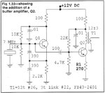
As already pointed out, you probably wouldn't use that oscillator configuration at 100MHz but answering your specific point, I would use the same values while accepting they are not critical to the oscillator functions. You could short out the 100 Ohm resistor and omit the capacitor completely if you were sure the supply impedance was low enough and it would make almost no difference to operation. If I really did build that circuit at 100MHz my main concern would be the properties of the 100nF capacitor, I would ensure it was a type that worked well at high frequencies or alternatively connect a good HF one in parallel with the existing 100nF. When you work at frequencies like 100MHZ the deficiencies of some capacitor constructions becomes significant, some types start to show higher than expected impedance and thus may not be good at keeping the collector at ground signal potential.

Brian.
 

I continue my reading in the book, and I will ask some questions…..

fig6.jpg
fig7.jpg
fig8.jpg

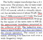
Q6: Now we have a 2.3KΩ at the collector of Q2, and the 50 Ω load is reflected to be 50*16 =800 ohm, My question is why the designer did not make the ratio 12:2, so we have
50*36 = 1800 ohm? I think it's the best and we can transfer greater power?

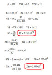
Q7: To calculate the input impedance (Zin) of the buffer (Q2 stage)

fig9.jpg

Is Zin (=3.4K) big enough to not load the oscillator?
Thank you very much
 

Q6: Now we have a 2.3KΩ at the collector of Q2, and the 50 Ω load is reflected to be 50*16 =800 ohm, My question is why the designer did not make the ratio 12:2, so we have 50*36 = 1800 ohm? I think it's the best and we can transfer greater power?

The answer is given in your fig.8: blue underlined. Means the primary inductive reactance of the transformer shouldn't have much impact, if the output load impedance changes (from 50Ω). In terms of greater power transfer, however, I think you're right.

Q7: To calculate the input impedance (Zin) of the buffer (Q2 stage)
Is Zin (=3.4K) big enough to not load the oscillator?

No, I think it's too low for loading from the base (in parallel to the crystal). The input of the second stage should be connected from the emitter (via 100pF), which has a much lower output impedance than the base.
 

Status
Not open for further replies.

Similar threads

Part and Inventory Search

Welcome to EDABoard.com

Sponsor

Back
Top